A hollow-core photonic crystal fiber resonator gyroscope based on free-form surface lens coupling

A technology of hollow-core photonic crystals and curved lenses, which is applied in the field of inertial sensing technology and integrated optics, can solve the problems of less lens reports, reduce the volume and installation difficulty, eliminate the need to adjust the optical path, improve reliability and adapt to the environment sexual effect

Active Publication Date: 2022-05-27
ZHEJIANG UNIV
View PDF7 Cites 0 Cited by
  • Summary
  • Abstract
  • Description
  • Claims
  • Application Information

AI Technical Summary

Problems solved by technology

Most of the current spatial light coupling schemes are a combination of plane beam splitters and general lenses, and there are relatively few reports on lenses designed by free-form surfaces.

Method used


Image

  • A hollow-core photonic crystal fiber resonator gyroscope based on free-form surface lens coupling
  • A hollow-core photonic crystal fiber resonator gyroscope based on free-form surface lens coupling
  • A hollow-core photonic crystal fiber resonator gyroscope based on free-form surface lens coupling

Examples


preparation example Construction

[0041] The preparation process of the optical fiber resonant gyroscope of the present invention comprises the following steps:

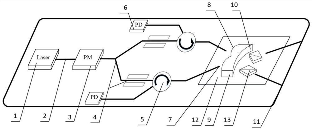
[0042] 1) Connect the optical transmission system, including a narrow linewidth laser light source 1, a first polarization-maintaining fiber 2, a phase modulator 3, a Y-waveguide 4, a circulator 5, and a photodetector 6.

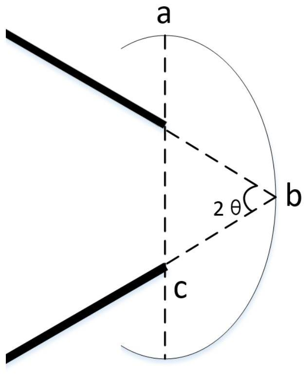
[0043] 2) Design the free-form surface lens coupler 9 . The second surface 10 is an ellipsoid surface, and the head and tail end surfaces of the hollow-core optical fiber ring 11 are at the two foci of the long axis of the ellipsoid, which can be coupled to each other after being reflected by the ellipsoid surface. The intersection of the extension lines at both ends of the hollow-core fiber ring 11 coincides with the center of the ellipsoid.

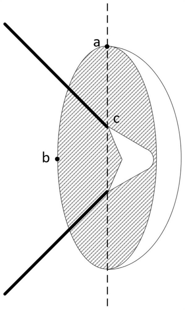
[0044] 3) According to the designed second surface 10, the first surface 8 is designed with a free-form surface, and the first surface 8 can be designed with a bicinczernike surface, so tha...

Embodiment

[0049] In the hollow-core photonic crystal fiber resonator gyroscope based on the free-form surface lens in this embodiment, the first polarization-maintaining fiber 2 is HC-1550-02 type, the center wavelength of the narrow linewidth laser light source 1 is 1550 nm, and the material of the free-form surface lens coupler 9 for BK7;

[0050] like figure 1 As shown, the light emitted by the narrow linewidth laser light source 1 enters the first polarization-maintaining fiber 2, and the phase modulator 3, the Y-waveguide 4, the circulator 5, and the photodetector 6 are sequentially arranged along the optical path direction. The free-form surface lens coupler 9, the polarization beam splitting prism 13, and the hollow fiber ring 11 form a resonant cavity. The second polarization-maintaining fiber 7 , the free-form surface lens coupler 9 , the polarization beam splitting prism 13 , and the head and tail end faces of the hollow-core fiber ring 11 are jointly mounted on an etched sil...


PUM

PropertyMeasurementUnit
wavelengthaaaaaaaaaa
reflectanceaaaaaaaaaa

Abstract

The invention discloses a hollow-core photonic crystal fiber resonant gyroscope based on free-form surface lens coupling. In the present invention, the light emitted by the narrow-linewidth laser light source passes through the first polarization-maintaining optical fiber and then modulated by the phase modulator to reach the Y waveguide. The Y waveguide divides the light into two beams of light with equal light intensity. After the circulator exits from the corresponding second polarization-maintaining fiber, it passes through the free-form surface lens coupler and the polarization beam splitting prism to couple and then enters the hollow-core fiber ring; a part of the light in the hollow-core fiber ring is reflected by the free-form surface lens coupler in the Resonance occurs in the ring of the hollow-core fiber ring, and another part of the light in the hollow-core fiber ring passes through the free-form surface lens coupler and then returns to the second polarization-maintaining fiber, passes through the corresponding circulator, and then reaches the corresponding photodetector. The invention has high integration, fewer coupling parts, reduces relative position error between components, has a more compact overall structure, improves the reliability and environmental adaptability of the fiber optic gyroscope, and has simple manufacturing process and high stability.

Description

technical field [0001] The invention belongs to the field of inertial sensing technology and integrated optics, and is a hollow-core photonic crystal fiber optic gyroscope in a space light coupling mode. Background technique [0002] With the development of inertial technology, the application field has higher and higher requirements on the volume and weight of the inertial system, and the design of integrated, miniaturized, low-cost and high-stability optical gyroscopes has become inevitable. Compared with traditional single-mode fiber, polarization-maintaining fiber has lower insertion loss, less nonlinearity, and is insensitive to environmental changes. In recent years, polarization-maintaining fibers have been increasingly used in the fabrication of resonator gyroscopes. However, the current optical fiber fusion splicing process is not compatible with polarization-maintaining fibers, and a high insertion loss often occurs when the solid-core optical fiber and the polari...

Claims


Application Information

Patent Timeline
Patent Type & Authority Patents(China)
IPC IPC(8): G01C19/72G01C25/00
CPCG01C19/72G01C19/721G01C25/005
Inventor 佘玄范文申何良陈侃毕然舒晓武
Owner ZHEJIANG UNIV
Why Eureka
Try Eureka