Diaphragm type pressure tank

A pressure tank and diaphragm type technology, applied in the field of pressure vessels, can solve the problems of high connection strength, good sealing, affecting the normal operation and service life of water pumps, etc.

Pending Publication Date: 2021-08-20
杭州亦正水处理设备有限公司
View PDF0 Cites 0 Cited by
  • Summary
  • Abstract
  • Description
  • Claims
  • Application Information

AI Technical Summary

Problems solved by technology

[0005] The invention solves the problem that the existing pressure tank is welded by carbon steel, and the inner membrane and the carbon steel are fixed by hot rolling, which easily leaves welding micropores in the hot rolling part of the welding machine, causing pressure drop and affecting the adjustment of the water volume of the pressure tank And pressure capacity, which in turn affects the normal operation and service life of the water pump. A diaphragm pressure tank is provided. The two tanks are made of high-strength plastic, and the two tanks are sealed and connected by plastic welding. , high connection strength, good sealing, and can withstand large internal pressure. When the two tanks are sealed and welded, the inner membrane is fixed by extrusion to ensure that there will be no micropores at the fixed place of the inner membrane.

Method used


Image

  • Diaphragm type pressure tank
  • Diaphragm type pressure tank
  • Diaphragm type pressure tank

Examples


Embodiment

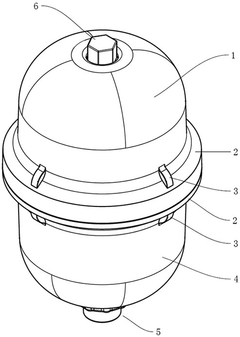
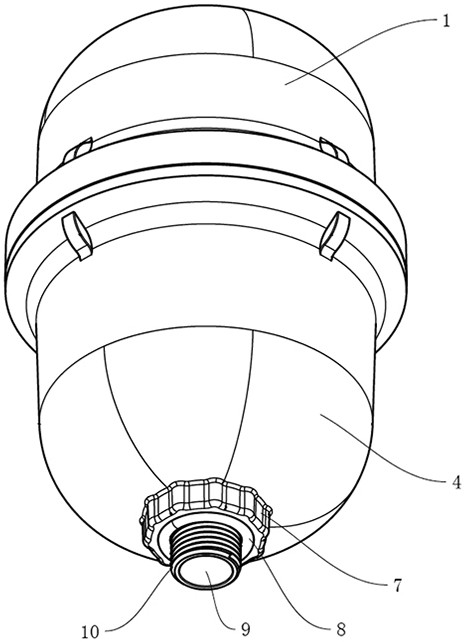
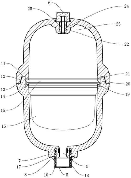
[0027] Such as figure 1 figure 2 image 3 As shown, a diaphragm-type pressure tank includes two half-tanks made of high-strength plastics, the two half-tanks are respectively a gas half-tank 1 and a water half-tank 4, and each half-tank has a docking port With an arc-shaped bottom, the butt joints of the two half-tanks face each other and are sealed and fixed by plastic welding. The bottom of the arc-shaped bottom is provided with a through hole, and a valve core 24 is arranged at the through hole of the air half-tank to form an air hole 25 and a water hole. The outer jacket is provided with a sealing cover. The through hole of the water half-tank is provided with a threaded connection column 10 to form a water hole 9, and a dust cover is placed outside the water hole. A bowl-shaped inner membrane 16 is arranged inside the pressure tank, and the bowl mouth of the inner membrane is turned outward to form an inner membrane connecting edge 30, and a pressure ring 15 is arrang...


PUM


Abstract

The invention relates to a diaphragm type pressure tank. The diaphragm type pressure tank comprises two half tank bodies made of plastic, wherein each half tank body is provided with a butt joint opening and an arc-shaped bottom, the butt joint openings of the two half tank bodies are opposite and are sealed and fixed in a plastic welding mode, through holes are formed in the bottoms of the arc-shaped bottoms, a valve core is arranged at the through hole of one half tank body to form an air hole, a threaded connecting column is arranged at the through hole of the other half tank body to form a water hole, a bowl-shaped inner film is arranged in the pressure tank, a bowl opening of the inner film is turned outwards to form an inner film connecting edge, a pressing ring is arranged between the two half tank bodies, the pressing ring is clamped when the two half tank bodies are welded and fixed, the pressing ring extrudes the inner film connecting edge to form sealed connection, and the inner film divides the interior of the pressure tank into a water chamber and an air chamber which are independent of each other. According to the diaphragm type pressure tank, the half tank bodies are made of plastic materials, so that water erosion is avoided, the inner wall does not need to be protected, the two butt joints are welded, sealed and fixed oppositely in a plastic welding mode, the sealing effect is good, the overall strength is high after sealing, the pressure balance requirement is met, and the service life is long.

Description

technical field [0001] The invention belongs to the field of pressure vessels, in particular to a diaphragm type pressure vessel. Background technique [0002] The expansion tank is used in the closed water circulation system to balance the water volume and pressure, and avoid frequent opening of the safety valve and frequent replenishment of the automatic water replenishment valve. The expansion tank not only holds the expansion water, but also acts as a water supply tank. After the water pump is started, it supplies water to the pipe network, and the excess water is stored in the tank, and the water level in the tank rises, and the air in the tank is affected. Compression increases the pressure. When the pressure in the tank reaches the specified upper limit pressure value, the indicator of the electric contact pressure gauge connected by the pipeline and the top of the tank is connected to the upper limit contact, a signal is sent, the power is cut off, and the pump is s...

Claims


Application Information

Patent Timeline
Patent Type & Authority Applications(China)
IPC IPC(8): F16J12/00
CPCF16J12/00
Inventor 汤亦根
Owner 杭州亦正水处理设备有限公司
Why Eureka
Try Eureka