
Method for depositing core layer of optical fiber preform with gradient refractive index profile

A graded refractive index and optical fiber preform technology, which is applied in manufacturing tools, glass manufacturing equipment, etc., can solve problems such as uneven distribution of axial parameters, affecting optical performance of optical fibers, and deviation from ideal profiles, etc., to achieve implementability and operability Strong, improved preparation accuracy and effective rod length, simple and effective method

Active Publication Date: 2021-08-24
YANGTZE OPTICAL FIBRE & CABLE CO LTD
View PDF6 Cites 1 Cited by
  • Summary
  • Abstract
  • Description
  • Claims
  • Application Information

AI Technical Summary

Problems solved by technology

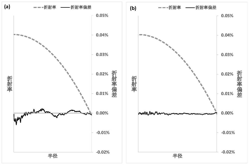
In the actual preparation, due to factors such as the speed fluctuation of the moving parts, the axial temperature distribution curve, the heating process of the reaction gas at the feed inlet, and the airflow fluctuation at the outlet, the axial deposition process of the mandrel will deviate from the ideal situation, especially The parameters of the core rod near the feed end (IS) and discharge end (OS) or near the turning point of motion will deviate from the ideal profile, resulting in uneven distribution of axial parameters, affecting the optical performance of the drawn optical fiber, and resulting in waste fiber rate Increase

Method used


Image

  • Method for depositing core layer of optical fiber preform with gradient refractive index profile
  • Method for depositing core layer of optical fiber preform with gradient refractive index profile
  • Method for depositing core layer of optical fiber preform with gradient refractive index profile

Examples


Embodiment Construction

[0039] In order to make the object, technical solution and advantages of the present invention clearer, the present invention will be further described in detail below in conjunction with the accompanying drawings and embodiments.

[0040] For the convenience of introducing content of the present invention, some terms are defined:

[0041] Mandrel: a preform comprising a core and part of the cladding;

[0042] Flowmeter (Mass Flow Controller, MFC): Provide accurate reactants (such as GeCl 4 、C 2 f 6 etc.) gas flow stabilization device with automatic flow control;

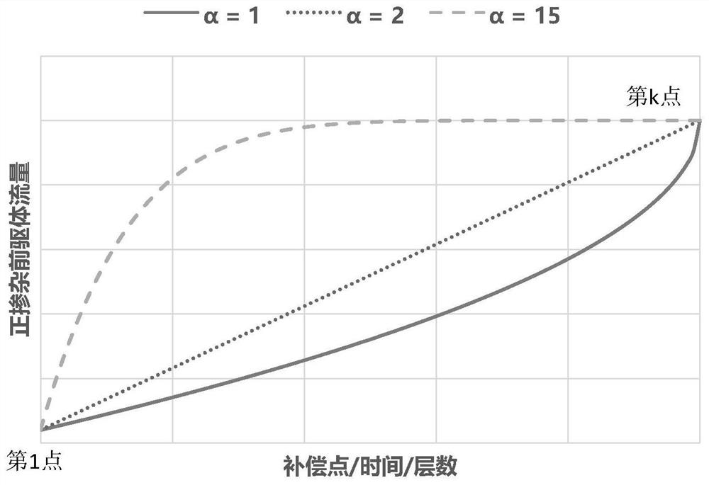
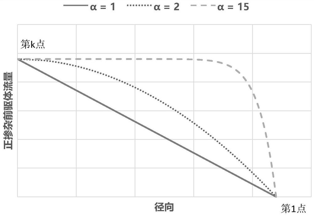
[0043] Doping deposition calibration: According to the dopant flow control data and the refractive index profile of the master rod, the software program is used to calculate the response relationship between the refractive index of the section and the dopant flow rate during the deposition process, and the ideal profile recalculated according to the above response relationship is required Flow rate, k×(m+1) flow c...


PUM

PropertyMeasurementUnit
lengthaaaaaaaaaa

Abstract

The invention relates to a method for depositing a core layer of an optical fiber preform with a gradient refractive index profile, which comprises the following steps of clamping a quartz glass tube or a target rod on a rotary chuck, axially reciprocating a microwave resonant cavity or a flame blast burner along the quartz glass tube or the target rod, and introducing reaction gas by controlling the opening degree of a flow meter to form a doped quartz glass deposition layer. The method is characterized in that a whole core layer deposition area is divided into k*(m+1) matrix point locations, a doped deposition vector of each point location is a calibrated doped deposition vector after a mother rod is measured and calculated, and the calibrated doped deposition vector is used for controlling and adjusting the opening degree of a reaction gas flow meter, and the opening control and adjustment of the flow meter are continuously and gradually changed among the point positions. The axial consistency of the core rod can be controlled and improved while the radial precision of the core layer is controlled and improved, so that the preparation precision and the effective rod length of the core layer of the gradient refractive index optical fiber preform rod are improved, and the qualified ratio of optical fiber output is improved.

Description

technical field [0001] The invention relates to a method for depositing a core layer of an optical fiber prefabricated rod with a graded refractive index profile, and belongs to the technical field of optical fiber prefabricated rod manufacturing. Background technique [0002] The optical fiber preform required for the production of graded-index optical fiber can be prepared by PCVD (Plasma Chemical Vapor Deposition) or MCVD (Modified Chemical Vapor Deposition) in the tube or OVD (Outside Vapor Deposition) in the tube. Through a certain way, such as SiCl is introduced into the high-purity quartz glass tube or outside the tube. 4 , O 2 、GeCl 4 Such high-purity reactants are excited by a microwave source resonator or a flame torch for chemical reaction and vapor deposition to form a transparent quartz glass deposition layer. The reaction formula for preparing the graded-index fiber core rod is as follows: [0003] SiCl 4 +O 2 = SiO 2 +2Cl 2 [0004] GeCl 4 +O 2 =GeO...

Claims


Application Information

Patent Timeline
Patent Type & Authority Applications(China)
IPC IPC(8): C03B37/014C03B37/018
CPCC03B37/0142C03B37/01815
Inventor 肖武丰黄荣张安林尹旭峰王海鹰王润涵
Owner YANGTZE OPTICAL FIBRE & CABLE CO LTD
Learn More