
Power module structure integrated with a current sensor

A technology of power module and integrated current, which is applied in the directions of only measuring current, converting AC power input to DC power output, measuring current/voltage, etc., and can solve the problems that cannot meet the application of vehicle-mounted drive power modules, are prone to changes, and have high power density.

Pending Publication Date: 2021-08-24
ZHENGHAI GRP CO LTD
View PDF0 Cites 1 Cited by
  • Summary
  • Abstract
  • Description
  • Claims
  • Application Information

AI Technical Summary

Problems solved by technology

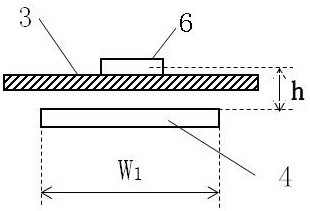
In the actual manufacturing process, when the current sensor is installed on the AC busbar, if the distance h between the two components deviates, the current measurement error will become larger
In addition, when this structure is applied to places with large vibrations such as new energy vehicles, the distance h is likely to change due to the influence of vibrations, and the measurement error of the current value will also increase.
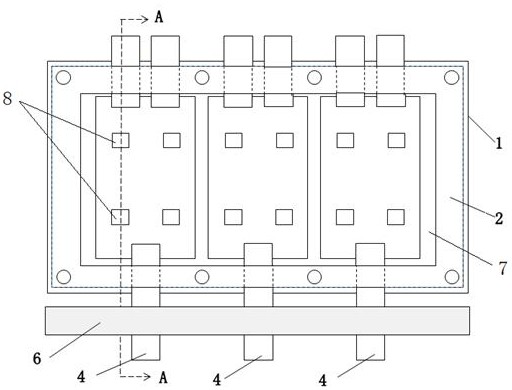
[0007] like figure 2 and image 3 As shown, in the traditional new energy vehicle inverter, the current sensor 6 is usually used to detect the current value of the AC busbar 4 in the three-phase AC controller. The traditional power module consists of a radiator 1, a plastic case 2, and a copper-clad ceramic substrate 7 Composed of a wafer 8, a copper-clad ceramic substrate 7 is arranged on the surface of the radiator 1, a wafer 8 is arranged on the copper-clad ceramic substrate 7 to form a control circuit, and a plastic case 2 is arranged on the radiator 1 and covers the copper-clad ceramic substrate 7. The busbar 4 is connected to the copper-clad ceramic substrate 7, and the control board 3 of the controller is located on the top surface of the plastic case 2. Since the power module and the current sensor 6 are two independent components, the detection signal of the current sensor 6 needs to be transmitted to the control board 3, the signal line is generally used to transmit the detection signal to the control board 3; the current sensor 6 needs to be installed in a fixed position and the AC busbar 4 needs to pass through the current sensor 6, so the controller needs to reserve a part of the space for installing a fixed current sensor. The sensor 6; and because the current signal is transmitted by the signal line, the current signal is easily disturbed by the external environment or other signals, and is affected by the vibration of the vehicle, and the relative displacement between the current sensor 6 and the AC busbar 4 will occur. Reduce the reliability of new energy vehicle inverters
At this stage, new energy vehicle drive controllers require higher power density and lower cost. The independent arrangement of power modules and current sensors in the past can no longer meet the application of vehicle drive power modules.

Method used


Image

  • Power module structure integrated with a current sensor
  • Power module structure integrated with a current sensor
  • Power module structure integrated with a current sensor

Examples


Embodiment Construction

[0033] Example Figure 2 to Figure 7 As shown, the power module structure of the integrated current sensor of the present invention includes a radiator 1, a plastic case 2, a copper-clad ceramic substrate 7, a wafer 8, a cover plate 22 and an AC busbar 4, and the copper-clad ceramic substrate 7 is arranged on the The surface of the heat sink 1, the wafer 8 is set on the copper-clad ceramic substrate 7 to form a control circuit, the plastic case 2 is set on the heat sink 1 and covers the copper-clad ceramic substrate 7, the AC The busbar 4 is connected to the copper-clad ceramic substrate 7 and extends out of the plastic case 2, the cover plate 22 is arranged on the top surface of the plastic case 2, and the structure B also includes a current sensing chip 5, a current sensing board 10 and A metal shield 9, the current sensing chip 5 is welded to the current sensing board 10, the current sensing board 10 is arranged on the plastic casing 2 and faces the AC busbar 4 protruding f...


PUM

PropertyMeasurementUnit
areaaaaaaaaaaa

Abstract

The invention discloses a power module structure integrated with a current sensor.The structure comprises a radiator, a plastic shell, a copper-clad ceramic substrate, a wafer, a cover plate and an alternating current busbar, the copper-clad ceramic substrate is arranged on the surface of the radiator, the wafer is arranged on the copper-clad ceramic substrate to form a control circuit, and the plastic shell is arranged on the radiator and wraps the copper-clad ceramic substrate. The alternating-current busbar is connected with the copper-clad ceramic substrate and extends out of the plastic shell; the cover plate is arranged on the top surface of the plastic shell; the structure further comprises a current sensing chip, a current sensing plate and a metal shielding cover. The current sensing chip is welded on the current sensing plate, and the current sensing plate is arranged on the plastic shell and directly faces the alternating current busbar extending out of the plastic shell; the metal shielding cover wraps the alternating current busbar and the current sensing plate, and the current sensing chip detects a current signal of the alternating current busbar. According to the structure, the integration level of the power module and the current sensor is improved, acquired current signals are prevented from being interfered or other signals are prevented from being interfered, the current sampling precision and the sampling reliability are improved, the power density of the power module is ensured, and the cost is reduced.

Description

technical field [0001] The invention relates to the technical field of power semiconductors, in particular to a power module structure integrating a current sensor. Background technique [0002] The power module is a combination of wafers packaged into a whole according to certain functions. It has the advantages of small size and high power density, so it has a wide range of applications in the field of new energy vehicles. With the development of new energy vehicles with high power and long battery life, the application environment of power modules is becoming increasingly harsh, and the integration of power modules has attracted widespread attention. [0003] Such as figure 1 As shown, usually the output signal of the current sensor is connected to the control board and detects the current signal flowing through the AC busbar. When the current sensor detects the current of the AC busbar, according to the formula (1), [0004] (1) [0005] Among them, B is the magneti...

Claims


Application Information

Patent Timeline
Patent Type & Authority Applications(China)
IPC IPC(8): G01R19/00G01R1/04G01R1/18H02M1/00H02M7/00H05K7/20H05K9/00
CPCG01R1/04G01R1/18G01R19/0092H02M1/00H02M7/003H05K7/20H05K9/0007
Inventor 毛先叶孙靖雅唐玉生
Owner ZHENGHAI GRP CO LTD
Learn More