Composite-vision-based intelligent flat plate groove cutting system and method

An intelligent cutting and visual technology, applied in manipulators, program-controlled manipulators, manufacturing tools, etc., can solve the problems of low cutting accuracy, failure to meet welding requirements, enlargement of workpiece size deviation, etc., to ensure stability and reliability, Guaranteed accuracy, guaranteed accuracy

Active Publication Date: 2021-08-27
芜湖行健智能机器人有限公司 +1
View PDF9 Cites 6 Cited by
  • Summary
  • Abstract
  • Description
  • Claims
  • Application Information

AI Technical Summary

Problems solved by technology

[0002] At this stage, most enterprises still adopt the Teach-then-Play method for flat bevel cutting, that is, for the same type of parts, the first part needs to be taught and used as a template for subsequent workpiece cutting. It is necessary to align and fix the workpiece with the template, and the robot will automatically repeat the cutting procedure, which will not only lead to cumbersome online programming process, high labor cost, low efficiency, unsafe and other disadvantages, but also the following key problems: (1) manual confirmation The cutting position and cutting accuracy of the bevel are completely determined by the visual inspection of the instructor; (2) Even if the parts meet the characteristics of large batches, small batches, and consistent dimensions, it is inevitable that cutting deformation will occur when the pre-sequence steel plate is unloaded, resulting in the deformation of the steel plate. In case of unevenness, warping, etc., the cutting trajectory will deviate from the actual contour of the workpiece, which will further amplify the size deviation of the workpiece after bevel cutting, especially affecting the accuracy of the size of the blunt edge, resulting in secondary defects in the workpiece. Product rate greatly increased
The disadvantage of the technology involved in this patent is that only the camera is used to collect the target point cloud model of the workpiece to be processed, and then the workpiece is beveled according to the point cloud model to match the target workpiece template, and the workpiece is not further accurately identified Positioning and precise correction of the cutting track, the cutting accuracy is not high
The technical deficiencies involved in this patent are: (1) Due to the influence of the blanking accuracy of sheet metal parts, even the actual size of the same type of parts will have deviations. Only using 3D vision system and 2D vision system to correct the position of parts is a problem. Insufficient, especially when the deviation of the cutting shape or the cutting angle is too large, the cutting edge melts and sags, or the corners are rounded, because the actual space contour of the workpiece cannot be obtained, the cutting trajectory and cutting pose are not corrected, which will lead to The cutting accuracy, especially the reserved size of the blunt edge is too large or too small, which cannot meet the actual welding requirements; (2) The 2D vision system is used to carry out secondary fine positioning of the workpiece to be cut before loading, and after loading the material is no longer corrected. The workpiece on the cutting workbench is accurately corrected for its position and posture. This method can improve the flatness of the cutting workbench, the calibration accuracy of various related equipment, the repeated positioning accuracy of the handling robot, and even the structural form and assembly accuracy of the end picker. All put forward higher requirements, otherwise it will be difficult to ensure the accuracy of the position coordinates of the workpiece to be cut on the cutting table, which will seriously affect the cutting accuracy of the groove of the flat part

Method used


Image

  • Composite-vision-based intelligent flat plate groove cutting system and method
  • Composite-vision-based intelligent flat plate groove cutting system and method
  • Composite-vision-based intelligent flat plate groove cutting system and method

Examples


Embodiment 1

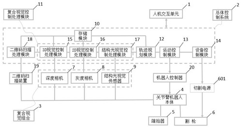
[0055] like figure 1 As shown, a compound vision-based intelligent cutting system for flat bevels designed by the present invention is characterized in that it includes a human-computer interaction unit 1, an overall control system 2, a compound vision combination 3 connected to the overall control system, and an articulated arm robot Body 4, end picker 5 and torch 6 connected with articulated arm robot body 4;

[0056] The composite vision combination 3 includes a depth camera 7, a gray scale camera 8 and a structured light vision sensor 9;

[0057] The overall control system 2 includes a storage module 10, a compound vision control processing module 11, a trajectory planning module 12, a motion control module 13 and an equipment control module 14;

[0058] The storage module 10 is used to store 3D model data and cutting process data of all parts to be cut; the storage module can also be set in the upper database.

[0059] The compound vision control processing module 11 in...

Embodiment 2

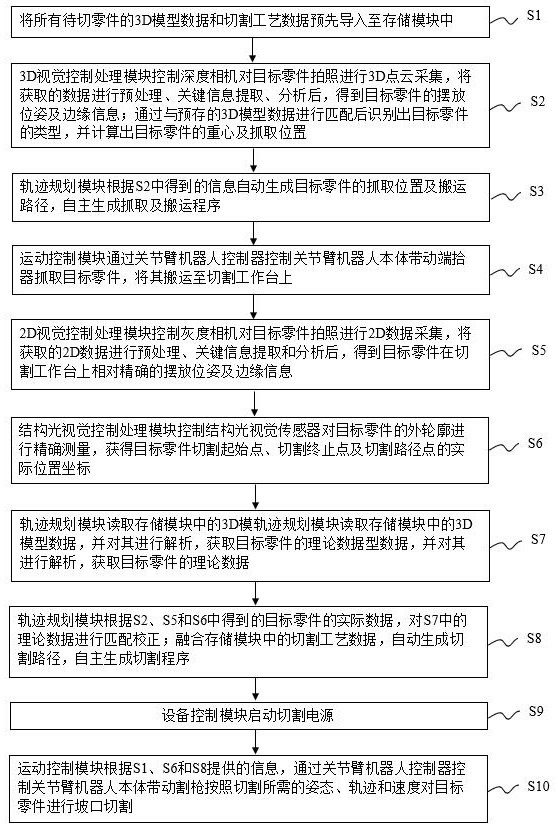
[0069] like figure 2 As shown, a compound vision-based intelligent cutting method for flat bevels includes the following steps:

[0070] S1, pre-importing the 3D model data and cutting process data of all parts to be cut into the storage module 10;

[0071] S2, the 3D vision control processing module 15 controls the depth camera 7 to take pictures of the target part to collect 3D point clouds, preprocess the acquired data, extract key information, and analyze to obtain the position and edge information of the target part; After matching with the pre-stored 3D model data, identify the type and position of the target part, and calculate the center of gravity and grasping position of the target part;

[0072] S3, the trajectory planning module 12 automatically generates the grasping position and the conveying path of the target part according to the information obtained in S2, and autonomously generates the grasping and conveying program;

[0073] S4, the motion control module...


PUM


Abstract

The invention belongs to the field of industrial intelligence, and particularly relates to a composite-vision-based intelligent flat plate groove cutting system. The system comprises a man-machine interaction unit, an overall control system, a composite vision combination connected with the overall control system, an articulated arm robot body, an end picker connected with the articulated arm robot body, and a cutting gun. The composite vision combination comprises a depth camera, a gray scale camera and a structured light vision sensor. The overall control system comprises a storage module, a composite visual control processing module, a trajectory planning module, a motion control module and an equipment control module. The storage module is used for storing 3D model data and cutting process data of all parts to be cut. The composite visual control processing module comprises a 3D visual control processing module, a 2D visual control processing module and a structured light visual control processing module. According to the composite-vision-based intelligent flat plate groove cutting system, autonomous feeding and discharging of the target parts are achieved by applying the 3D vision technology, precise position deviation correction, cutting track deviation correction and cutting pose deviation correction are conducted on the target part by fusing the 2D vision technology and the structured light vision technology, autonomous generation of a cutting program is achieved, and then the full-autonomous intelligent cutting system is achieved, and the ideal precision of groove cutting of the flat plate parts is ensured.

Description

technical field [0001] The invention belongs to the field of industrial intelligence, and in particular relates to an intelligent cutting system and method for flat bevels based on compound vision. Background technique [0002] At this stage, most enterprises still adopt the Teach-then-Play method for flat bevel cutting, that is, for the same type of parts, the first part needs to be taught and used as a template for subsequent workpiece cutting. It is necessary to align and fix the workpiece with the template, and the robot will automatically repeat the cutting procedure, which will not only lead to cumbersome online programming process, high labor cost, low efficiency, unsafe and other disadvantages, but also the following key problems: (1) manual confirmation The cutting position and cutting accuracy of the bevel are completely determined by the visual inspection of the instructor; (2) Even if the parts meet the characteristics of large batches, small batches, and consist...

Claims


Application Information

Patent Timeline
Patent Type & Authority Applications(China)
IPC IPC(8): B25J9/16B25J11/00
CPCB25J9/1602B25J9/1664B25J9/1697B25J11/0055
Inventor 王宗义纪宇熊新炎
Owner 芜湖行健智能机器人有限公司
Why Eureka
Try Eureka