Anti-resonance hollow-core optical fiber

A technology of hollow-core fiber and anti-resonance, which is applied in cladding fiber, light guide, optics, etc., can solve the problems of difficult to control the thickness, position and shape of the dielectric layer, increase the cladding nodes of the fiber, and affect the characteristics of the fiber. Effects of damage threshold, increased transmission bandwidth, and reduced material absorption loss

Active Publication Date: 2021-08-27
JIANGXI NORMAL UNIV
View PDF15 Cites 2 Cited by
  • Summary
  • Abstract
  • Description
  • Claims
  • Application Information

AI Technical Summary

Problems solved by technology

Later, it was found that nesting multi-layer dielectric tubes inside the dielectric tube of the anti-resonance layer can make the confinement loss lower than the surface scattering loss, but because the current preparation conditions are not developed enough, the thickness, position and shape of each dielectric layer are difficult to be accurate control
W. J. Belardi et al [W. Belardi, Design and properties of hollow antiresonant fibers for the visible and near infrared spectral range. J. Lightw. Technol., 2015, 32:4497~4503] prepared nested negative curvature hollow core fiber, The loss is 175dB / km, because the wall thickness of the two dielectric tubes in the cladding is quite different, and the position and size of the small dielectric ring are different, which affects its fiber characteristics
In 2018, Wang Yingying and others from Beijing University of Technology [Shou-fei Gao, Ying-ying Wang, Wei Ding, et al. Hollow-core conjoined-tube negative-curvature fiber with ultralow loss[J]. Nature Communications, 2018, 9(1 )] published a connected tubular multi-resonator AR-HCF structure with nodes. The researchers did not try to remove the cladding nodes, but weakened the coupling between the cladding mode and the core mode at the nodes to reduce the fiber loss through precise control. However, this technology will increase the nodes in the fiber cladding, which will cause too many cladding modes. During the fiber preparation process, it needs to be precisely adjusted to avoid the influence of the cladding modes at the nodes.

Method used


Image

  • Anti-resonance hollow-core optical fiber
  • Anti-resonance hollow-core optical fiber
  • Anti-resonance hollow-core optical fiber

Examples


Embodiment 1

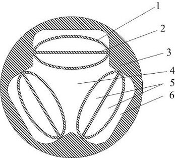
[0021] The invention provides a multi-resonant layer hollow-core optical fiber, such as figure 1 As shown, the optical fiber is composed of a first-type dielectric tube 1, a first-type dielectric layer 2 and a second-type dielectric tube 3, including a high-refractive-index cladding region and a low-refractive-index core region. The first-type dielectric tube 1 and the first-type medium layer 2 are connected to the second-type medium pipe 3 . The area surrounded by the outer wall of the first-type dielectric tube close to the core area forms the first-type hole 4, which is the fiber core area. A second-type hole 5 is isolated between the first-type medium pipe 1 and the first-type medium layer 2 , and a third-type hole is isolated between the first-type medium pipe 1 and the second-type medium pipe 3 .

[0022] The first-type medium pipe 1 and the second-type medium pipe 3 are connected in a tangential manner; both ends of the first-type medium layer 1 are connected to the se...

Embodiment 2

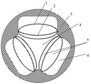
[0025] The invention provides a multi-resonant layer hollow-core optical fiber, such as figure 2 As shown, the optical fiber is composed of a first-type dielectric tube 1, a first-type dielectric layer 2 and a second-type dielectric tube 3, including a high-refractive-index cladding region and a low-refractive-index core region. The first-type dielectric tube 1 and the first-type medium layer 2 are connected to the second-type medium pipe 3 . The area surrounded by the outer wall of the first-type dielectric tube close to the core area forms the first-type hole 4, which is the fiber core area. A second-type hole 5 is isolated between the first-type medium pipe 1 and the first-type medium layer 2 , and a third-type hole is isolated between the first-type medium pipe 1 and the second-type medium pipe 3 .

[0026] The first-type medium pipe 1 and the second-type medium pipe 3 are connected in a tangential manner; both ends of the first-type medium layer 1 are connected to the s...

Embodiment 3

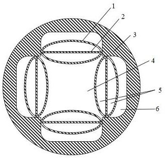
[0028] The invention provides a multi-resonant layer hollow-core optical fiber, such as image 3 As shown, the optical fiber is composed of a first-type dielectric tube 1 , a first-type dielectric layer 2 and a second-type dielectric tube 3 , including a cladding region with a high refractive index and a core region with a low refractive index. Both the first-type medium pipe 1 and the first-type medium layer 2 are connected to the second-type medium pipe 3 . The area surrounded by the outer wall of the first-type dielectric tube close to the core area forms the first-type hole 4, which is the fiber core area. A second-type hole 5 is isolated between the first-type medium pipe 1 and the first-type medium layer 2 , and a third-type hole is isolated between the first-type medium pipe 1 and the second-type medium pipe 3 .

[0029] The first-type medium pipe 1 and the second-type medium pipe 3 are connected in a tangential manner; both ends of the first-type medium layer 1 are co...


PUM


Abstract

The invention provides an anti-resonance hollow-core optical fiber. The anti-resonance hollow-core optical fiber is composed of a first-type dielectric tube, a second-type dielectric tube and a first-type dielectric layer and comprises a cladding region with high refractive index and a fiber core region with low refractive index; the first-type dielectric tube and the first-type dielectric layer are both connected to the second-type dielectric tube; the area surrounded by the outer wall, close to the core region, of the first type dielectric tube is a fiber core region (a first-type hole); a second-type hole is isolated between the first-type dielectric tube and the first-type dielectric layer; and a third-type hole is isolated between the first-type dielectric tube and the second-type dielectric tube. The fiber core of the optical fiber has a negative curvature boundary; the optical fiber is provided with a plurality of anti-resonance layers; the cladding of the optical fiber has no nodes, so that the leakage loss is effectively reduced; the optical fiber has no loss peak value caused by transverse nodes, so that transmission bandwidth is increased; besides, optical fiber modes are mainly distributed in air holes, so that the material absorption loss of the optical fiber can be effectively reduced, the damage threshold of the optical fiber is improved, and high-power laser and terahertz waves can be effectively transmitted.

Description

technical field [0001] The invention relates to the field of optical fiber design, in particular to an anti-resonant hollow-core optical fiber. Background technique [0002] The application of optical fiber can realize high-speed and large-capacity communication, and it is an indispensable information transmission technology. With the development of optical fiber transmission technology, anti-resonant hollow-core optical fiber is becoming more and more dominant in realizing high-bandwidth, low-loss optical transmission. This fiber is hollow, and the transmission rate of optical signals can be 30% higher than that of traditional solid-core fibers, and can reach 99.7% of the speed of light, which also makes it an important driver for the development of optical fiber communications, lasers, nonlinear optics and other fields force. [0003] The researchers hope that AR-HCF can reduce losses by simply adding anti-resonant layers like HC-PBGF. Later, it was found that nesting m...

Claims


Application Information

Patent Timeline
Patent Type & Authority Applications(China)
IPC IPC(8): G02B6/032G02B6/02
CPCG02B6/032G02B6/02314
Inventor 左翔宇祝远锋姬丹丹王少华罗皓洋
Owner JIANGXI NORMAL UNIV
Why Eureka
Try Eureka