Micron-scale linear focusing scanning micro-spectral optical coherence tomography system

A technology of optical coherence tomography and scanning microscopy, applied in the field of three-dimensional microscopic imaging of biomedicine, can solve the problems of low resolution and imaging efficiency, no imaging features and advantages, etc., to improve imaging efficiency, reduce dispersion difference, The effect of ensuring spatial consistency

Pending Publication Date: 2021-08-31
NANJING NORMAL UNIVERSITY
View PDF0 Cites 2 Cited by
  • Summary
  • Abstract
  • Description
  • Claims
  • Application Information

AI Technical Summary

Problems solved by technology

[0003] The purpose of the patent of the present invention is to provide a micron-scale line focus scanning microspectral optical coherence tomography system to overcome the traditional spectral optical coherence tomography technology that has no imaging features and advantages and has low resolution and imaging efficiency limitation

Method used


Image

  • Micron-scale linear focusing scanning micro-spectral optical coherence tomography system
  • Micron-scale linear focusing scanning micro-spectral optical coherence tomography system
  • Micron-scale linear focusing scanning micro-spectral optical coherence tomography system

Examples


Embodiment 1

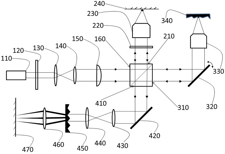
[0021] refer to figure 1 , a micron-scale line focus scanning microspectral optical coherence tomography system, comprising: a light source light path, a reference arm light path, a sample arm light path, and a spectrometer light path. The optical path of the light source includes: a broadband light source 110 , a spectral filter 120 , a beam expander lens group ( 130 , 140 ), a cylindrical mirror 150 , and a first surface 160 of a beam splitter. The wavelength range of the broadband light source is 500-600nm. In the light path of the light source, the light emitted by the broadband light source 110 passes through the instrument successively in the order of the spectral filter 120, the beam expander lens group (130, 140), the cylindrical mirror 150, and the first surface 160 of the beam splitter.

[0022] The optical path of the reference arm includes: the second surface 210 of the beam splitter, a neutral density filter 220 , a microscope objective lens 230 , and a plane mir...

Embodiment 2

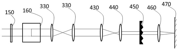
[0026] refer to figure 2 , which is the imaging principle optical path of a two-dimensional image with color distribution presented on the two-dimensional photosensitive array on the horizontal plane, including: cylindrical mirror 150, beam splitter 160, microscopic objective lens 330, and light beam converging lens group ( 430 , 440 ), a grating 450 , a lens 460 , and a two-dimensional photosensitive array 470 . The light emitted by the cylindrical lens 150 group passes through the instrument successively in the order of cylindrical lens 150, beam splitter 160, microscopic objective lens 330, microscopic objective lens 330, light beam converging lens group (430, 440), grating 450 , a lens 460, and a two-dimensional photosensitive array 470. On the horizontal plane, the light passes through the cylindrical mirror to keep parallel and enters the beam splitter. After exiting the beam splitter, it hits the scanning galvanometer, then reflects from the scanning galvanometer, and...

Embodiment 3

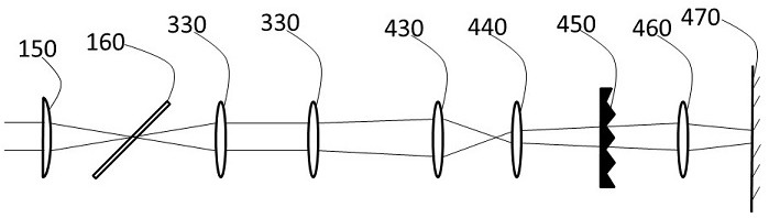
[0028] refer to image 3, which is the imaging principle optical path of a two-dimensional image with color distribution presented on the two-dimensional photosensitive array on the vertical plane, including: cylindrical mirror 150, beam splitter 160, microscopic objective lens 330, and light beam converging lens Group (430, 440), grating 450, lens 460, two-dimensional photosensitive array 470. The light emitted by the cylindrical lens 150 group passes through the instrument successively in the order of cylindrical lens 150, beam splitter 160, microscopic objective lens 330, microscopic objective lens 330, light beam converging lens group (430, 440), grating 450 , a lens 460, and a two-dimensional photosensitive array 470. On the vertical plane, the light passes through the cylindrical mirror and then focuses on the beam splitter, then passes through the beam splitter and multiple reflections, diverges and irradiates on the microscopic objective lens, and then irradiates para...


PUM

PropertyMeasurementUnit
wavelengthaaaaaaaaaa

Abstract

The invention discloses a micron-sized linear focusing scanning micro-spectral optical coherence tomography system. The system comprises a light source light path, a reference arm light path, a sample arm light path, a spectrograph light path and a beam splitter. A first surface of the beam splitter communicates with the light source light path, a second surface of the beam splitter communicates with the reference arm light path, a third surface of the beam splitter communicates with the sample arm light path, and a fourth surface of the beam splitter communicates with the spectrometer light path. A broadband illumination light source uses a spectrum in a range of 500-600 nm. Backscattering information of different depths of an imaging sample is modulated in the interference spectrum, and depth information of the sample can be obtained by performing Fourier transform and further processing on the backscattering information. Through a linear illumination mode, side-cut images of a tested sample can be acquired in parallel on a two-dimensional array camera. The system is mainly used in the field of three-dimensional microscopic imaging.

Description

technical field [0001] The invention relates to a micro-spectrum optical coherence tomography imaging system of micron-scale line focus scanning, which belongs to the technical field of three-dimensional microscopic imaging of biomedicine. Background technique [0002] Spectral Optical Coherence Tomography (SOCT) is a three-dimensional tomographic imaging technique that can reconstruct images in the depth direction by collecting interference spectra and transforming them through Fourier transform. Compared with other medical imaging methods, OCT technology has the advantages of high resolution, non-contact, non-invasive measurement, low cost, and simple system. The core components of the OCT system are broadband illumination source, Michelson interferometer and spectrometer. However, the traditional spectral optical coherence tomography technology has no imaging characteristics and advantages, and has the limitations of low resolution and imaging efficiency. Therefore, in o...

Claims


Application Information

Patent Timeline
Patent Type & Authority Applications(China)
IPC IPC(8): A61B5/1455G02B21/00
CPCA61B5/14551G02B21/002
Inventor 邢芳俭沈加伟狄云松聂守平徐寅林
Owner NANJING NORMAL UNIVERSITY
Why Eureka
Try Eureka