Method for producing vias having variable sidewall profile

A plasma etching, semiconductor technology, used in semiconductor/solid-state device manufacturing, electrical components, circuits, etc., can solve problems such as reducing productivity and economic benefits

Inactive Publication Date: 2003-12-31
SIEMENS AG
View PDF3 Cites 2 Cited by
  • Summary
  • Abstract
  • Description
  • Claims
  • Application Information

AI Technical Summary

Problems solved by technology

However, this method requires several processes and several processing chambers, thereby reducing productivity and economic efficiency

Method used


Image

  • Method for producing vias having variable sidewall profile
  • Method for producing vias having variable sidewall profile
  • Method for producing vias having variable sidewall profile

Examples


example 1

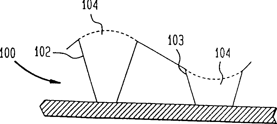
[0045] Using a commercially available plasma etch chamber with a wall temperature of 35°C and a cathode support temperature of 20°C, vias were created in a silicon dioxide layer deposited on a titanium nitride (TiN) layer ,Such as image 3 shown, under the following conditions:

[0046] Pressure 300 millitorr (mTorr)

[0047] Nitrogen substrate pressure 8 Torr

[0048] Power 900 watts

[0049] Magnetic induction 80 gauss

[0050] The first step in creating a sloped opening in the silica layer is to pass 100 standard cubic centimeters (sscm) of CHF through the chamber for 90 seconds 3 and 20 sccm of argon. The result was a sidewall slope of about 69° and an opening diameter of about 980 microns.

[0051] Second stage gas flow changed to 30sccm CHF 3 and 100 seem argon and continue for 90 seconds. As a result, the inclination angle of the sidewall is about 80°, and the diameter of the opening at the bottom of the via hole is about 610 microns. image 3 is a photomicrogr...

example 2

[0052] Using the process conditions of Example 1, the duration of the first stage is 120 seconds, the diameter of the formed opening is about 1000 microns, and the inclination angle of the side wall is about 67°. The chamber pressure of the second etching phase was changed from 100 mTorr to 300 mTorr, and the duration was 60 seconds. The second stage forms a via bottom opening with a diameter of approximately 600 microns and a sidewall inclination angle of approximately 81°. Figure 4 is the micrograph of the result. Additionally, a smooth transition is formed between the initial etched corner and the second etched corner. No obvious incision exists.

[0053] In this way, only by changing two parameters, the etching time and the proportion of etching gas, the shape of the sidewall of the opening can be changed at will to form openings of different sizes with different inclination angles. Smoother sidewall slopes can be obtained by gradually changing the etch gas ratio. In ...


PUM


Abstract

A via opening having a varying sidewall taper can be made by varying the proportion of polymers deposited on the sidewalls during the etch. For example, the proportion of a fluorine-containing etch gas and an inert carrier gas can be changed to etch smooth variably tapered vias in silicon oxide to ensure complete filling of the vias by a subsequently deposited layer of material.

Description

technical field [0001] The present invention relates to a plasma etching process for forming vias in a semiconductor substrate. Background technique [0002] In the production of semiconductor devices, many devices, such as transistors, are fabricated on a semiconductor substrate, such as a silicon wafer. These transistors utilize conductive metal lines, typically aluminum, to make electrical connections. Metal contact areas are also deposited on the substrate to connect the device to other devices or interposers. [0003] Since a large number of devices on a substrate have been made smaller and closer together, the design size has been able to reach less than 1 micron or even less than 0.5 micron, so more devices can be fabricated on different layers of a silicon wafer superior. The first group of devices is fabricated and electrically connected, and then a dielectric layer, such as SiO, is deposited on this layer of devices. 2 . To reach the via lines and contact area...

Claims


Application Information

Patent Timeline
Patent Type & Authority Patents(China)
IPC IPC(8): H01L21/302H01L21/3065H01L21/311H01L21/768
CPCH01L21/76804H01L21/31116H01L21/3065
Inventor 约肯·哈尼贝克
Owner SIEMENS AG
Why Eureka
Try Eureka