Heat removal type supercritical water treatment reactor for oily sludge and operation method thereof

A technology of supercritical water and reactors, which is applied in the fields of oxidation treatment of sludge, chemical instruments and methods, water/sludge/sewage treatment, etc. It can solve the problems of too fast heating of reactors, difficulty in continuous operation, and easy coking, etc. Achieve good economy and safety, prevent overheating of reaction, and good environmental protection

Inactive Publication Date: 2021-08-31
CHINA PETROLEUM & CHEM CORP +2
View PDF5 Cites 1 Cited by
  • Summary
  • Abstract
  • Description
  • Claims
  • Application Information

AI Technical Summary

Problems solved by technology

[0006] In order to solve the disadvantages of low efficiency in the treatment of oily sludge in the prior art, difficulty in continuous operation, easy coking, and difficulty in controlling the release of a large amount of heat during the reaction process, the present invention provides a heat extraction type supercritical water treatment oily sludge reactor and Its operation method overcomes the technical problems of easy coking in the oxidation reaction of oily sludge, difficulty in continuous operation, excessive heat rise of the reactor due to the large amount of heat released by the reaction, etc., and realizes long-term continuous non-toxic oxidation of oily sludge in a supercritical water environment. Hazardous treatment

Method used


Image

  • Heat removal type supercritical water treatment reactor for oily sludge and operation method thereof
  • Heat removal type supercritical water treatment reactor for oily sludge and operation method thereof
  • Heat removal type supercritical water treatment reactor for oily sludge and operation method thereof

Examples


Embodiment Construction

[0057] The present invention will be further described below in conjunction with the accompanying drawings.

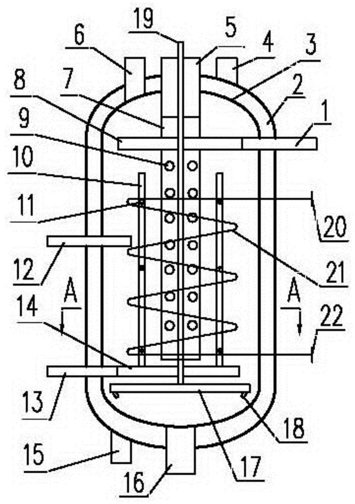
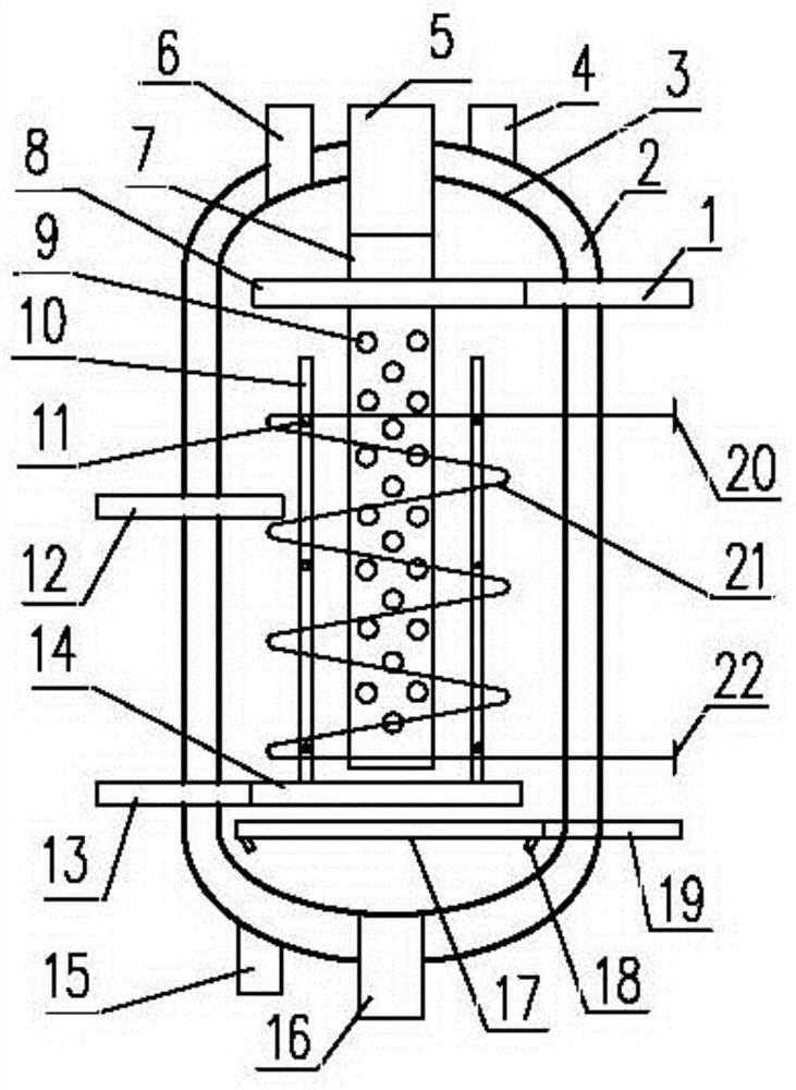
[0058] figure 1 It is a structural schematic diagram of the present invention, as shown in the figure,

[0059] The heat extraction type supercritical water treatment oily sludge reactor provided by the present invention includes a vertical cylindrical reaction chamber 3, and a sludge distribution pipe 8 located in the reaction chamber 3 and arranged coaxially with the reaction chamber 3 from top to bottom. , heat-taking coil 21 and oxidant distribution pipe 14, sludge inlet 1, oxidant inlet 13, gas outlet 6, slurry outlet 16, heat-taking coil inlet 20, which are arranged on the reaction chamber 3 and communicate with the inside and outside of the reactor And the outlet 22 of the heat extraction coil, the sludge inlet 1 is located in the middle and upper part of the reaction chamber 3, the oxidant inlet 13 is located in the middle and lower part of the reaction chambe...


PUM

PropertyMeasurementUnit
diameteraaaaaaaaaa
diameteraaaaaaaaaa
widthaaaaaaaaaa

Abstract

The invention discloses a heat removal type supercritical water treatment reactor for oily sludge and an operation method thereof. The reactor comprises a reaction cavity, a sludge distribution pipe, a heat removal coil pipe, an oxidant distribution pipe, a sludge inlet, an oxidant inlet, a gas outlet, a slag slurry outlet, a heat removal coil pipe inlet and a heat removal coil pipe outlet, wherein the sludge distribution pipe, the heat removal coil pipe and the oxidant distribution pipe are positioned in the reaction cavity and are coaxially arranged with the reaction cavity from top to bottom; the sludge inlet, the oxidant inlet, the gas outlet, the slag slurry outlet, the heat removal coil pipe inlet and the heat removal coil pipe outlet are formed in the reaction cavity and communicate with the inside and the outside of the reactor; the sludge inlet extends into the reaction cavity and is connected with the sludge distribution pipe; sludge distribution holes are formed in the pipe wall of the sludge distribution pipe; the oxidant inlet extends into the reaction cavity and is connected with the oxidant distribution pipe; oxidant distribution holes are formed in the pipe wall of the oxidant distribution pipe; and the heat removal coil pipe inlet and the heat removal coil pipe outlet extend into the reaction cavity and are respectively connected with the two ends of the heat removal coil pipe. The reactor of the invention overcomes the technical problems that in the oxidation reaction of the oily sludge, coking is prone to occurring, continuous operation is difficult, and the reactor is heated too fast due to a large amount of heat released in the reaction.

Description

technical field [0001] The invention belongs to the technical field of environmental protection, and in particular relates to a heat extraction type supercritical water treatment oily sludge reactor and an operation method thereof. Background technique [0002] Sewage treatment systems of oil fields and refineries and crude oil production, storage and transportation systems will generate a large amount of oily sludge. With the increasingly stringent environmental protection regulations and the continuous improvement of the environmental awareness of the whole society, the treatment of oily sludge has attracted more and more attention. The traditional treatment methods of oily sludge include landfill, composting, incineration, etc., but the landfill of sludge needs to occupy a large amount of space and cost a lot of freight, and pollute the environment and groundwater; In addition, the oily sludge may contain toxic and harmful substances such as heavy metals; the incineration...

Claims


Application Information

Patent Timeline
Patent Type & Authority Applications(China)
IPC IPC(8): C02F11/08C02F101/30
CPCC02F11/086C02F2101/30
Inventor 邓矛晁君瑞
Owner CHINA PETROLEUM & CHEM CORP
Why Eureka
Try Eureka