Sheath-core composite fiber with high melt index and preparation method and production equipment of fiber rod of sheath-core composite fiber

A high melt index, composite fiber technology, applied in fiber processing, fiber chemical characteristics, rayon manufacturing, etc., can solve the problems of uneven capillary structure, poor capillary water absorption effect, low production efficiency, etc., to ensure the capillary water absorption effect , high melt index, and the effect of ensuring water absorption performance

Active Publication Date: 2021-08-31
广东鑫球新材料科技有限公司
8 Cites 0 Cited by

AI-Extracted Technical Summary

Problems solved by technology

[0004] However, the above skin-core composite fibers still have the problems of high melting temperature required in the process of preparing fiber rods and uneven internal capillary structure after curing, which not only leads to low production ef...

Method used

In the present invention, because the melt index of cortex is improved, so the utilization ratio after cortex melting is obtained, avoided the problem that cortex melt index is low in the prior art and can not effectively form fiber rod after cortex melting, namely in the present invention Based on the high melting index of the skin layer, the components of t...

Abstract

The invention provides sheath-core composite fiber with a high melt index and preparation method and production equipment of a fiber rod of the sheath-core composite fiber. The fiber comprises a sheath layer and a core layer which are arranged from outside to inside; the sheath layer is prepared from a PE material and PP cooling master batch; the PP cooling master batch accounts for 10% of the sheath layer; the core layer is prepared from a PP material; and the melting point of the sheath layer is lower than that of the core layer. According to the invention, the sheath layer is prepared from the PE material and the PP cooling master batch, and the PP cooling master batch has the characteristics of reducing the extrusion temperature (namely reducing the melting point temperature) and improving the melt index of resin, so that the temperature difference between the sheath layer and the core layer is increased, and when the fiber rod is prepared, the hot melting efficiency of the sheath layer at the same temperature is higher than the hot melting efficiency of the sheath layer without the PP cooling master batch in the prior art; and meanwhile, due to the increase of the melt index, the molten sheath layer quickly flows, so that the uniformity of the internal capillary organization structure after setting and curing is ensured, and the capillary water absorption effect of the fiber rod is ensured.

Application Domain

Filament/thread formingConjugated synthetic polymer artificial filaments +2

Technology Topic

Melting Point TemperatureFiber +1

Image

  • Sheath-core composite fiber with high melt index and preparation method and production equipment of fiber rod of sheath-core composite fiber
  • Sheath-core composite fiber with high melt index and preparation method and production equipment of fiber rod of sheath-core composite fiber
  • Sheath-core composite fiber with high melt index and preparation method and production equipment of fiber rod of sheath-core composite fiber

Examples

  • Experimental program(1)

Example Embodiment

[0040] The present invention provides a high melt index have a sheath-core composite fiber, comprising from the outside in the skin and core layers are arranged, the skin cooling by PE and PP masterbatch made, accounting for the PP cooling Masterbatch 10% of the skin layer, the core layer being made of PP material, the melting point of the skin layer and below the melting point of the core layer.
[0041] Wherein the different peroxide content PP and PE masterbatch cooling material mixed in different proportions, to obtain a mixture, melt index was measured, as shown, with increased cooling masterbatch PP content, the melt index of the mixture of Table 1 exhibit significantly the increasing tendency, when the content is less cooling masterbatch, and 2.5% to 2% or less flowability improving effect PE material, and when the addition amount of cooling masterbatch exceeds 10%, PE 2.5% so that the material has a melt index more substantial increases, and therefore, preferably, the PP cooling masterbatch peroxide content of 2.5%.
[0042]
[0043] Wherein, A is the amount of peroxide, B mixing ratio, the number of C, M average;
[0044] A melting point in the present invention the skin layer is 110-130 ° C; melting point compared with the prior art PE material is 120-140 degrees C, the melting point of the present invention, the skin layer is significantly reduced, thereby cooling PP based masterbatch with a reduced extrusion temperature (i.e., lowering the melting point temperature), melt index improving properties of the resin, the temperature difference between the skin layer and the core layer is increased, so that in the preparation of fiber rods, thermal efficiency of the skin at the same temperature than the prior art PP masterbatch of cortical high cooling efficiency without addition of a hot melt, and because increase the melt index, the melt after rapid cortical flow, thus ensuring uniformity of shape after curing an internal capillary structure of the tissue, thus ensuring the fiber rods capillary suction effect, the melting point of PP material is 150-170 degrees Celsius.
[0045] Since the skin layer in the present invention, melt index is increased, so the utilization is obtained after melting the skin, avoiding the problems of the prior art due to the low melt index skin can not effectively form a fiber melt stick after the skin layer, i.e. the skin by the present invention, high melt index base on the skin layer only 20% -30% of the total amount of components, the components of the core layer accounts for 70% -80% of the total, with respect to the prior art, 40% -60% the thickness of the skin layer is significantly reduced, so that not only reduces the manufacturing cost, but also effectively protect the fibers in the water-absorbing shaped rod.
[0046] The method of preparing the above technical solution to cool PP masterbatch to: quantitative DTBP was dissolved in acetone, poured into PP resin thoroughly stirring and mixing, a melt extruder with a blender to a twin screw extruder and pelletized, preparative oxide content of 2.5% PP cooling masterbatch; the preparation method of the prior art, and is not specifically described herein.
[0047] Further, the skin layer mixture was prepared: The PP cooling Masterbatch 24h placed in a forced air oven dried to remove residual acetone, and the pellet surface moisture, PE material is dried in vacuo at 100 deg.] C 24h at 60 ℃, and before melt spinning, the masterbatch material mixing and cooling PE, PP cooling masterbatch to give a content of 10% mixture.
[0048] The present invention also provides a preparation method comprising applying the fiber rods of the core-sheath composite fibers of high melt index, comprising the steps of: texturing the core and sheath composite fiber ply warping, which depends on the number of plied be prepared fiber diameter rod; rod warping fiber ply directly into the shaping mold, and sequentially completion of the heating step and the setting step in the sizing die, the sizing device is provided to form a mold having a predetermined shape of the product, after heating the filaments by a single, cured to form the desired product bar; the invention the skin layer due to the high melting temperature and a low melt index, it is possible to complete the heating step and the shaping step directly in the casting mold, avoiding the prior art problems can not be completed in the first heating and melting shaping process and improve the production efficiency of fiber rods.
[0049] Preferably the heating temperature, the heating step is 130 ~ 145 ℃, the curing time setting step of 100-1000 seconds, during heating to melt the solidified skin stick to each other.
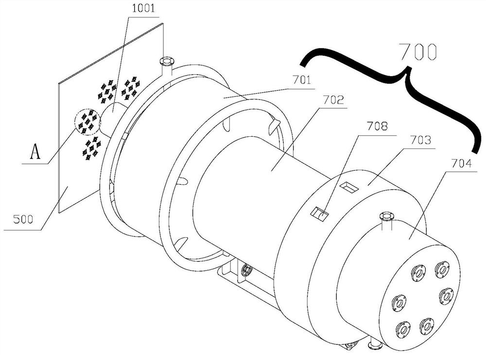
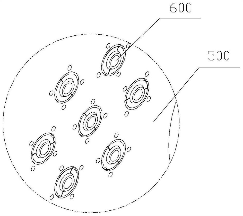
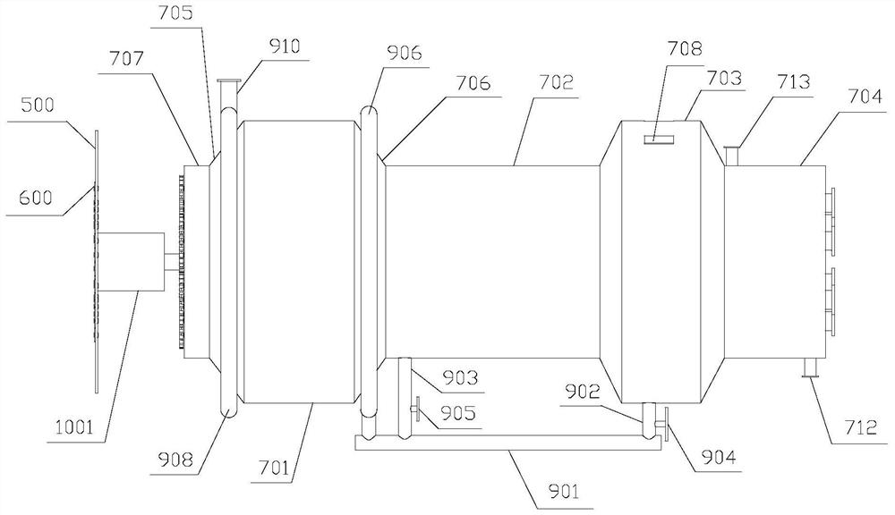
[0050] The present invention also provides a fiber prepared by the rods filament production equipment, such as Figure 1-18 , The tensioning mechanism comprising filaments direction of movement of the filaments disposed in sequence, a first processing means 600 and wire fiber rods setting means, wherein the setting means comprises a fiber rods preheating section 801, a melt section 802, transition section 803 and the cooling section 804, and the preheating section 801, the movement direction of the molten section 802, transition section 803 and the cooling section 804 are sequentially configured along the material 700 inside the cabinet. Housing section 700 is located in the preheating section 801 and the melt 802 through the first location spaced from the separator 709, 700 is located in the housing section 802 and a melt transition section 803 through the second separator 710 spaced apart positions, located in the transition housing 700 position segment 803 and the cooling section 804 through the third separator 711 spaced apart from, the housing 700 with respect to the preheating zone 801, a melt section 802, transition section 803 and the portion 804 of the cooling section are formed preheating chamber 701, the chamber 702 melt , transition chamber 703 and cooling chamber 704, 710 on the second separator defines a plurality of communication holes 714 for communicating the fuser 703 and the transition chamber. Upper and lower ends of the cooling chamber 704 are configured with a cooling water outlet 713 and cooling water inlet 712, cooling water enters from the lower end of the cooling cavity 704, and then the fibers are cooled rod 1300 is discharged from the upper cooling chamber 704. The inlet ventilation heat transfer system 702 are in communication with the melting chamber and the transition chamber 703, the chamber 702 and the heat of the molten transition chamber 703 via ventilation preheating chamber into the heat transfer system 701, and heat exchange with the material in the preheating chamber 701. The working principle and advantages of the present invention is that: a plurality of high melt index of its respective double filament payout reel filaments by tensioning means, such that each double filament remains tensioned state, and adjustable according to the needs bis tension layer filaments, after processing through the first double-filament wire rod mechanism enters the fiber 600 after setting means, the first processing means 600 wire rod shaped fiber carding means, each other to avoid double filament interleaved winding, or where double knotted filaments appear, fiber rods setting means is a predetermined number of double filaments melt formed fiber rods 1300, the final shape by a cutting device cutting the fiber rods 1300; wherein the fiber rods styling the mechanism comprises a preheating zone 801, a melt section 802, transition section 803 and cooling section 804 respectively function as: a preheating zone 801 is preheated through this section of double filaments, the preheating temperature is generally 58-75 ℃, it is preheated in a double filament fusion melting section 802, generally at a temperature of 155-185 ℃, after fiber rods 1300 formed by heat fusion for their initial loss in transition section 803, and then enter the cooling section 804, 1300 the fiber rods cooled to normal temperature and a temperature below; ventilation heat transfer system of the present invention is provided in the transition part of the heat chamber 703 within fiber rods 1300 dissipated heat melting chamber 702 and preheating chamber 701 to the supply, such that heat is fully utilized, and according to the specific needs of a temperature, the heat within the molten suction control chamber 702, so that the melt chamber 702 to maintain heat within the preheating chamber 701 within a predetermined range.
[0051] As a preferred embodiment of the present invention, such as Figure 4-5 Shown, comprises a preheating zone 801 along the diameter direction of movement of the material feed reduction poly cones, the above-described melting section 802, transition section 803 and the tubular structure 804 are in turn connected to the cooling section, the radius of the tubular structure with a poly equal to the radius of the small-diameter end of the tapered tube material, the melting section 802 with the outer tubular structure in which the electrical heating wire 805 extending axially. The present invention, in order to improve the strength and yield of the product, the preheating zone 801, a melt section 802, transition section 803 and cooling section 804 is integrally formed structure, and connected at the smooth transition segments, each segment of smooth inner surface without burrs . Wherein, in order to improve efficiency, the number of fibers into a plurality of rod shaped bodies, fibers preheating section rod shaped means 801 is mounted in a housing 700 fixed to the front end of the mounting opening 707, and the mounting opening 707 is not connected preheating section 801 the seal holding portion, these fibers stick to the setting means are arranged uniformly in the circumferential direction of the casing 700 in the housing 700, so that complete synchronization can be achieved plurality of fibers stick 1300. The present invention, in order to ensure a plurality of double-filament fibers into the rod shaped means separated from each other, each of the inlet end of the preheating period setting mechanism fiber rods 801 are respectively connected to a second wire management means 1100, setting means when the rod enters the fiber a plurality of double filaments gradually polymerized and remains parallel to the integration, the second processing means 1100 are held stationary wire fiber rods and setting mechanism 802 in the melting section; fiber rods when it is desired to enter a plurality of setting means gradually double filaments and twisting during the melt fusion stage 802, this method of increasing the strength of the fiber rods 1300, such as Figure 6-7 Shown, each second processing means 1100 and the wire fiber rods of the shaping means corresponding to the preheating zone 801 is rotatably connected to a drive motor 1001 through drive gear mounted on the output shaft 1002 which drives the second processing means 1100 filaments rotation , so that wear through the respective second processing means a plurality of wire twisting filaments 1100 integrally with each other. 1002 may be a portion of the second transmission wire processing means with the driving gear 1100 is connected to the other wire portion of the second processing means 1100 with the drive gear 1002 are independent, independent of each other, so that synchronization can produce two or more types of fibers stick 1300 herein refers to a variety of models of a different number of double filament, or a different winding form a parallel combination method of the above obtained fiber rods 1300.
[0052] As a preferred embodiment of the present invention, such as Figure 8-11As shown, the second rigid mechanism 1100 includes a circular mounting plate 1101 that is detachably attached to the circular mounting plate 1101, and a plurality of guide wire assemblies 1104 are mounted, and the wheel is uniformly constructed on the circumferential surface of the circular mounting plate 1101. The teeth 1102, the circular mounting plate 1101 meshing with the active gear 1002 thereon, and a connecting sleeve 1103 is configured on one end surface of the circular mounting plate 1101, and the connection sleeve 1103 is equipped with a bearing, and the connection sleeve 1103 passes The bearing is rotated within the inlet end of the preheating section 801. Wherein the guide wire assembly 1104 is identical to the structure of the first rigid mechanism 600, the first ration mechanism 600 is mounted on the body front plate 500, and the guide wire assembly 1104 is mounted on the circular mounting plate 1101, the implementation As an example of a guide wire assembly 1104, the guide wire assembly 1104 includes a fixing member and a guide wire member 11043, and the fixing member is mounted on the circular mounting plate 1101, and the guide wire member 11043 is mounted inside the fixture, and the guide wire member 11043 has supplied Fiber wire passes through the guide wire; the fixture includes two mutually spliced ​​semi-fixing members, each semi-fixing member includes a connecting plate 11041 and a plug-in projection 11042, wherein the connecting plate 11041 is used for the circular mounting plate 1101. The connection is fixed, and the plugging projection 11042 is integrated with the connecting plate 11041 and is inserted within the junction of the circular mounting plate 1101, and the two-semi-sleeve is similar to each other, and there is a half-lifting chamber, two half-pack cavity. Mutual stitching constitutes a complete assembly chamber, and the outer surface of the guide is adapted to the assembly chamber. The double fiber wire passes through the guide, and when the bilateral fiber is changed in the direction of the double fiber, the guide member is deflected, and the bilateral fiber wire is avoided such that the obtained fiber rod 1300 is lowered, or double fiber wire. Cracking occurs before it is not melted, and it is necessary to replace or continue.
[0053] As a preferred embodiment of the present invention, such as Figure 3-4 As shown, the liquid heat transfer system includes a total tube 901, and the total tube 901 communicates with the transition chamber 703 and the molten cavity 702, respectively, in the first communication tube 902 and the second connecting tube, respectively. The first control valve 904 and the second control valve 905, the first control valve 904 and the second control valve 905 are mounted, respectively, and the first mounting portion 706 is constructed at one end of the preheating chamber 701 close to the molten chamber 702. The second mounting portion 705 is configured in the other end of the preheating chamber 701, and the first annular tube 906 is connected to the preheating chamber 701 in a first conduit 907 that is uniformly provided in the first mounting portion 706. The hot air is fully filled into the preheating chamber 701, and the second annular tube 908 communicates with the preheating chamber 701 in a second tube 909 that is uniformly provided along the second mounting portion 705, and is constructed on the second annular tube 908. The suction joint 910, the suction port of the exhaust fan is connected to the suction joint 910, and there is a discharge 708 in communication with the outside of the outer wall of the transition chamber 703. The exhaust fan is opened, most of the heat of the transition chamber 703, the small portion of the molten chamber 702 is mixed into the first annular tube 906 after mixing in the total tube 901, and the first annular tube 906 will be in the preheating chamber 701, heat The airflow will be discharged by the suction joint 910 by the suction joint 910 by the second annular tube 908 after heating the double fiber filament of the preheating section 801.
[0054] As a preferred embodiment of the present invention, such as Figure 13-18 As shown, the fiber wire tensioning mechanism includes interconnecting the tensioning portion and the guide wire portion, and the two can be a fixed connection, or an adjustable connection. In this embodiment, the adjustable connection is an example, and a plurality of first adjusting rods 101 are uniformly constructed along its circumferential direction, and there is a plurality of first in the tensioned portion. The two adjustment lever 301, the first adjustment lever 101 and the second adjustment lever 301 are connected together by the adjustment sleeve 302, and the two ends of the connection sleeve 1103 are respectively connected to the first adjustment lever 101 and the second adjustment lever 301, respectively. The tensioning portion and the guide wire provide a plurality of tension wheels 402 and a plurality of guide wire wheel 202 respectively provided, respectively, each of which sequentially passes the corresponding tension wheel 402 and a guide wire wheel 202.
[0055] As a preferred embodiment of the present invention, such as Figure 16 As shown, the guide wire portion includes a plurality of guide wire members 200, and these guide wire members 200 are mounted on the guide wire fixed circular plate 100, such as Figure 14 As shown, the guide wire member 200 includes a fixed seat 201 and a guide wire wheel 202, and the guide wire wheel 202 is rotated to be mounted on the stationary seat 201, such as Figure 17 As shown, a plurality of curved holes 102 are configured on the guide wire fixing circular plate 100, and each guide wheel 202 is slidably mounted on the guide wire fixed circular plate 100, respectively, in the fixed seat 201. The two linker 203 is configured, and the two connecting ear 203 is located on both sides of the arcuate hole 102, and the rotation shaft 204 is rotated between the two connecting ear 203, and the rotating shaft 204 is adapted to the curved hole 102 and can be in the curved shape. The holes 102 are rolled in the extending direction of the arc hole 102, and the fixing seat 201 is fastened to the guide wire fixed circular plate 100 by the lock screw 205. The operator can change the relative position of the guide wire member 200 and the guide wire to fix the circular plate 100 according to the position of the specific double-layer fiber, and thereby causing the double fiber wire to be successfully transmitted. like Figure 18 As shown, the tensioning portion includes a ring mounting lever 300 and a plurality of tension members 400, such as Figure 15 As shown, the tension member 400 includes a mount 401 and a tension wheel 402, each of which is mounted on the annular mounting rod 300, and the mount 403 is constructed, and the hoop 403 is set in the ring mounting On the rod 300, the hug 403 is fastened to the ring mounting rod 300 through the tension screw 404. The operator can adjust the tensioning member 400 on the ring mounting lever 300, and adjust the angle between the tension member 400 and the ring mounting lever 300 axis, that is, adjust the tensioning member 400 in the ring mounting rod 300. Turn a certain angle, its purpose is to make the tensioner 402 tension double-layer fiber to a predetermined degree.
[0056] As a preferred embodiment of the present invention, such as Figure 12 As shown, in order to smoothly convey the finished fiber rod 1300, a discharge roller 1200 is attached to the rear end of the casing 700 with respect to each of the fiber rods 1300, and the fiber rod 1300 is discharged to the roller 1200. The fiber stick type mechanism is derived.
[0057] The above is merely preferred embodiments of the invention, and is not limited to the present invention. It should be noted that in terms of ordinary skill in the art, several improvements and moisters can also be made without departing from the principles of the invention, and these improvements and moisters should also be considered as the scope of the present invention.

PUM

PropertyMeasurementUnit
Melting point110.0 ~ 130.0°C
Melting point150.0 ~ 170.0°C

Description & Claims & Application Information

We can also present the details of the Description, Claims and Application information to help users get a comprehensive understanding of the technical details of the patent, such as background art, summary of invention, brief description of drawings, description of embodiments, and other original content. On the other hand, users can also determine the specific scope of protection of the technology through the list of claims; as well as understand the changes in the life cycle of the technology with the presentation of the patent timeline. Login to view more.

Similar technology patents

Adjustable garden landscape irrigator

InactiveCN108029518AGuaranteed uniformityconducive to common development
Owner:安徽瀚一规划设计院有限公司

Biconical rotary vacuum drying system

ActiveCN102168909AGuaranteed uniformityUniform fineness
Owner:JIANGSU XIANFENG DRYING ENG

Classification and recommendation of technical efficacy words

Why Eureka
Try Eureka