Light pipeline lead-in optical cable and manufacturing method thereof

A technology that introduces optical cables and manufacturing methods, applied in the field of optical cable manufacturing, can solve problems such as low tensile strength and inconvenient construction of optical cables, and achieve the effects of ensuring tensile performance, improving waterproof performance, excellent mechanical properties and environmental applicability

Pending Publication Date: 2021-09-03
成都亨通光通信有限公司
View PDF0 Cites 0 Cited by
  • Summary
  • Abstract
  • Description
  • Claims
  • Application Information

AI Technical Summary

Problems solved by technology

[0004] In view of the above technical problems, the purpose of the present invention is to provide a light-duty pipeline lead-in cable, which aims to solve the technical problems of the existing lead-in cables that are not convenient for construction and low tensile strength, and provide a smaller outer diameter and lighter weight with excellent resistance. The light pipe with bending performance leads into the optical cable, which can effectively improve the utilization rate of the communication pipeline in the community and facilitate construction; it can also effectively improve the tensile strength of the optical cable; reduce the fault maintenance of the optical cable line by the operator, thereby reducing the investment cost

Method used


Image

  • Light pipeline lead-in optical cable and manufacturing method thereof
  • Light pipeline lead-in optical cable and manufacturing method thereof
  • Light pipeline lead-in optical cable and manufacturing method thereof

Examples


Embodiment 1

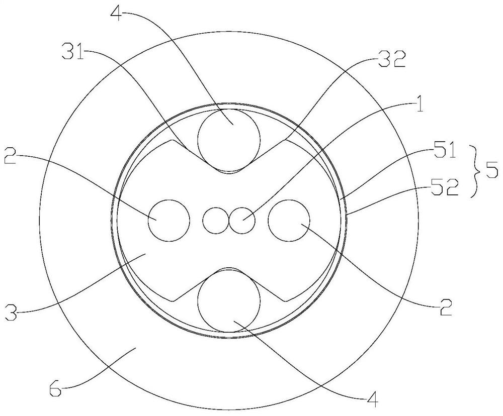
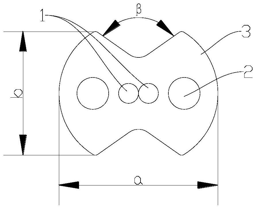
[0040] combine figure 1 and figure 2 As shown, this embodiment provides a light-duty pipe drop cable, which is mainly used in the home broadband communication system of newly built or old cells; the drop cable includes a butterfly cable subunit, a reinforcement 4, a water blocking layer 5 and an outer protective Layer 6, wherein the butterfly cable sub-unit includes a colored optical fiber 1, a butterfly sheath 3 wrapped in the colored optical fiber 1, and a strength member 2 embedded in the butterfly sheath 3, and the colored optical fiber 1 can be one or two , this embodiment takes two colored optical fibers 1 as an example to form an optical fiber ribbon; in this embodiment, a reinforcement 4 is respectively arranged between the gaps 31 of the butterfly wings on both sides of the butterfly cable subunit, and the reinforcement 4 is in a columnar structure and is connected with The colored optical fibers 1 are arranged side by side, and each reinforcing member 4 is arranged...

Embodiment 2

[0049] combine Figure 1 to Figure 4 As shown, this embodiment provides a manufacturing method of a light-duty duct drop cable, which is used to manufacture the light-duty duct drop cable in Embodiment 1. The manufacturing method at least includes the following steps:

[0050] colored fiber 1;

[0051] To make the butterfly cable unit, use the optical fiber and the strength member 2 to tightly sleeve the low-smoke and halogen-free fuel to form the butterfly cable unit; in this process, when the colored optical fiber 1 is tightly sleeved into the butterfly cable unit, it is necessary to strictly control the colored optical fiber 1 , The pay-off tension of the unit reinforcement 2; use a specific non-adjustable eccentric drawing tube mold to ensure that the optical fiber stripping force value can be stably maintained at 6N-9N;

[0052] A reinforcement 4 made of phosphating steel wire is respectively placed between the gaps 31 of the butterfly wings on both sides of the butterfl...


PUM

PropertyMeasurementUnit
diameteraaaaaaaaaa
angleaaaaaaaaaa

Abstract

The invention discloses a light pipeline leading-in optical cable and a manufacturing method thereof, and relates to the technical field of optical cable manufacturing, the leading-in optical cable comprises a butterfly cable subunit, a reinforcing piece and a water blocking layer, the butterfly cable subunit comprises an optical fiber, a butterfly sheath wrapping the optical fiber and the reinforcing piece embedded in the butterfly sheath, the butterfly cable subunits are respectively provided with a reinforcing piece between the gaps of the butterfly wings on the two sides; the reinforcing pieces are of a columnar structure, and each reinforcing piece is tangent to the side walls of the corresponding notches on the two sides of the reinforcing piece; the water blocking layer tightly wraps the outer sides of the butterfly cable subunits and the reinforcing parts to form a cable core structure, the cross section of the cable core structure is circular, and the reinforcing parts are tangent to the inner side of the water blocking layer; by implementing the technical scheme, the technical problems that an existing lead-in optical cable is inconvenient to construct and low in tensile strength are solved, the light pipeline lead-in optical cable which is smaller in outer diameter, lighter in weight and excellent in bending resistance is provided, construction is convenient, the tensile strength of the optical cable can be effectively improved, and then the input cost is reduced.

Description

technical field [0001] The invention relates to the technical field of optical cable manufacturing, in particular to a light duct lead-in optical cable and a manufacturing method thereof. Background technique [0002] The communication metropolitan area network has formed a basic transmission network covering cities, counties, and towns after the preliminary engineering construction, and has already taken shape, and the operating cost has gradually decreased; various regions have built a comprehensive service transmission network supporting big data and a metropolitan area data network. And the deployment of a complete urban optical cable network has created good conditions for meeting the needs of backup business access. With the development of the data service market and the increasing number of customers in the broadband integrated service smart community, the construction of the broadband access network in the community is imminent, and the intelligent high-speed informa...

Claims


Application Information

Patent Timeline
Patent Type & Authority Applications(China)
IPC IPC(8): G02B6/44
CPCG02B6/4433G02B6/443G02B6/4486
Inventor 唐子红司正中赵坤祥邱勇吴祥君刘杰王梦菲
Owner 成都亨通光通信有限公司
Why Eureka
Try Eureka