Microwave wireless energy transmission system

A technology of energy transmission and microwave wireless, applied in the direction of electrical components, circuit devices, etc., can solve the problems of high frequency requirements of microwave energy transmission signals, rectification efficiency and capacity of rectification circuits that cannot meet application-level requirements at the same time, and efficiency reduction.

Pending Publication Date: 2021-09-07
SHANGHAI DIANJI UNIV
View PDF6 Cites 0 Cited by
  • Summary
  • Abstract
  • Description
  • Claims
  • Application Information

AI Technical Summary

Problems solved by technology

[0004] In terms of power transmission, the DC output power of microwave rectifier circuits developed by most scholars is below 1w, which cannot meet the power supply requirements of watt-level terminals in application scenarios such as smart homes, telemedicine, and unmanned factories. Although the rectifier circuit can output a DC power of more than 1w, its circuit size is 180mm×180mm (about 1.5 times the free space wavelength corresponding to 2.45GHz). Such a large size makes the microwave rectifier circuit unable to communicate with the receiving terminal (such as Smartphones) and receiving array antennas (the distance between the array antenna elements is generally not greater than 1 times the wavelength) are well integrated together, and there are still the following deficiencies:
[0005] 1. It is difficult for the rectification efficiency and capacity of the rectification circuit to meet the application-level requirements at the same time
[0006] 2. If higher power transmission requirements are required, the size of the antenna will be limited to a large level, and it cannot be integrated with common powered terminals (such as mobile phones) on the market
[0007] 3. Microwave energy transmission has high requirements on signal frequency, and the efficiency will be greatly reduced if it deviates from the corresponding frequency band

Method used


Image

  • Microwave wireless energy transmission system
  • Microwave wireless energy transmission system
  • Microwave wireless energy transmission system

Examples


Embodiment

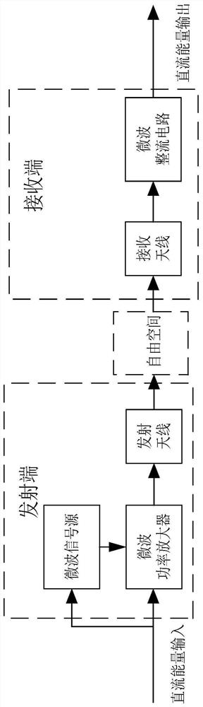
[0028] Such as figure 1 As shown, the present invention provides a microwave wireless energy transmission system. In the microwave wireless energy transmission system, the function of the receiving end is to receive the microwave energy directionally transmitted to the microstrip antenna in the air, and convert it into DC power and output it to the load. The device used to complete the receiving and conversion functions is called a rectifying antenna. The rectifying antenna is composed of two parts: the receiving antenna and the rectifying circuit. The receiving antenna is used to efficiently receive and transmit the microwave signal transmitted from the air to the rectifying circuit. Then the high-frequency microwave signal is converted into a DC signal and output to the load.

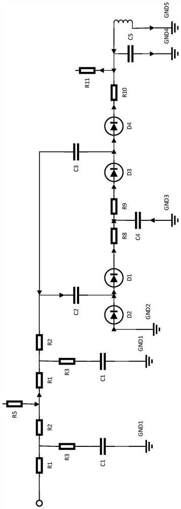
[0029] Such as figure 2 As shown, the rectifier circuit is composed of three parts: input filter, rectifier diode and output filter. The input filter is a low-pass filter, which is used to pass the ...


PUM


Abstract

The invention relates to a microwave wireless energy transmission system which comprises a transmitting end and a receiving end serving as a rectifying antenna. The transmitting end is used for transmitting microwave signals and comprises a microwave signal source, a microwave direct-current power amplifier and a transmitting antenna. The receiving end comprises a receiving antenna and a rectifying circuit. The receiving antenna receives directionally transmitted microwave signals from a free space, the microwave signals are rectified and converted into direct current signals through the rectifying circuit, and the direct current signals are sent to a load. Compared with the prior art, the energy transmission distance and environment limitation are solved, the existing wire connection type charging and wireless charging modes are changed, and the system facilitates life, improves efficiency, and greatly reduces power consumption cost.

Description

technical field [0001] The invention relates to the technical field of power electronics and energy transmission radio frequency, in particular to a microwave wireless energy transmission system. Background technique [0002] In the 1960s, research on microwave energy transmission technology was carried out abroad. In the past few decades, Europe and the United States have carried out a large number of experiments on microwave energy transmission. technology. Microwave energy transmission technology plays a very important role in systems such as satellite solar power stations, RFID (Radio Frequency Identification), and floating platforms. Among them, microwave rectifier circuit is the key in microwave energy transmission technology. For the current research on microwave rectifier circuits, most rectifier circuits are designed using Schottky diodes. The power capacity of a single Schottky diode with a large power capacity is about 20d Bm, and the efficiency of Schottky diod...

Claims


Application Information

Patent Timeline
Patent Type & Authority Applications(China)
IPC IPC(8): H02J50/20H02J50/27
CPCH02J50/20H02J50/27
Inventor 吴昊楠张海燕杨家泰张冰倩朱仁进
Owner SHANGHAI DIANJI UNIV
Why Eureka
Try Eureka