
Heavy truck new energy automobile power battery control system

A new energy vehicle, power battery technology, applied in control/regulation systems, battery/fuel cell control devices, electric vehicles, etc., can solve problems such as reducing fuel storage capacity, reducing system stability, and reducing control system sensitivity.

Inactive Publication Date: 2021-09-10
冯永瑞
View PDF0 Cites 0 Cited by
  • Summary
  • Abstract
  • Description
  • Claims
  • Application Information

AI Technical Summary

Problems solved by technology

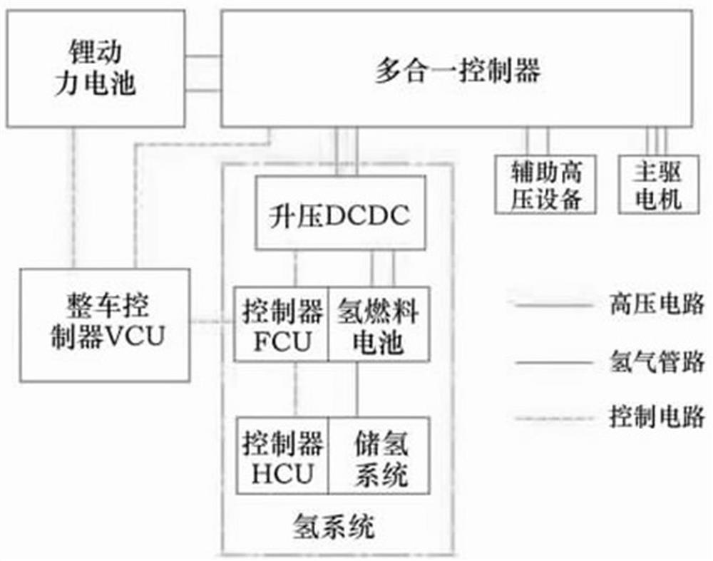
[0003] like figure 1 As shown, it is the technical solution of the existing battery control system. The entire control system is composed of three parts, the vehicle controller VCU, the controller FCU, and the controller HCU. There is no power auxiliary circuit around the three controllers, so it is difficult to ensure The stability of electric energy output, the controller HCU is closely connected with the fuel storage area, which reduces the capacity of fuel storage, and there is no direct control channel between the controller VCU and HCU, which reduces the sensitivity of the entire control system
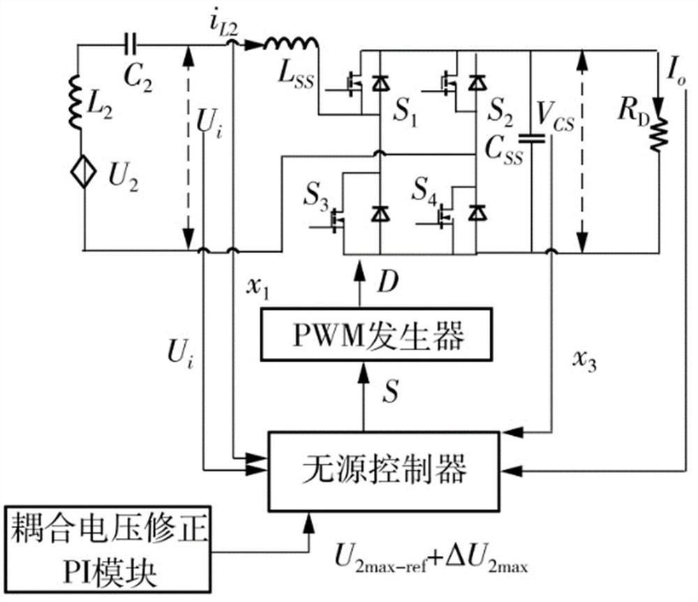
[0004] like figure 2 As shown, it is the existing technical solution of the passive control circuit. The passive controller needs to be controlled by the inductance L2 and the capacitance C2, so it will be affected by electromagnetic induction, so that the output signal will fluctuate and the stability of the system will be reduced.

Method used


Image

  • Heavy truck new energy automobile power battery control system
  • Heavy truck new energy automobile power battery control system
  • Heavy truck new energy automobile power battery control system

Examples


Embodiment Construction

[0018] The present invention will be further described below in conjunction with embodiment.

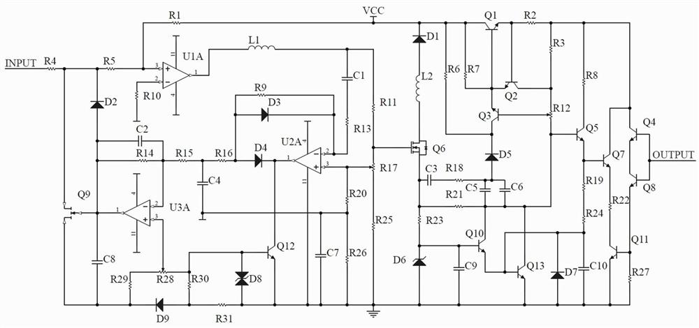
[0019] Such as image 3 As shown, the power battery control system for heavy truck new energy vehicles of the present application includes a feedback control stabilization input circuit, a passive controller control circuit, and an output power control circuit.

[0020] Feedback control stabilizes the input circuit. The current signal of the power battery flows into the amplifier U1A and the field effect transistor Q9 respectively through the resistor R4. The signal at both ends is stabilized through the diode D2. The high-precision resistor R5 increases the input impedance, and the accuracy of the current signal is also improved. The processed current signal continues to flow into the operational amplifier U3A, which reduces the degree of magnification reduction in the low frequency area and high frequency area, and broadens the passband. Finally, the current signal is output to the...


PUM


Abstract

The invention relates to a heavy truck new energy automobile power battery control system which comprises a feedback control stable input circuit, a passive controller control circuit and an output power control circuit. According to the heavy truck new energy automobile power battery control system and the feedback control stable input circuit, the purpose of reducing circuit noise and interference is achieved by improving the stability of the magnification times, the decline degree of the magnification times of a low-frequency area and a high-frequency area is reduced, and therefore the transmission band is broadened by about 1+AF times, and the stability of output voltage is improved. The passive controller control circuit reduces the self consumption of the circuit by controlling a flowing signal, and ensures that more limited electric quantity of the power battery can be provided for a load. The output power control circuit can keep the total output power of the power amplifier unchanged, the corresponding relation between the load impedance change and the output power is weakened, and the power control of the power battery is more accurate.

Description

technical field [0001] This application relates to the field of new energy sources for heavy trucks and power batteries, and specifically relates to a power battery control system for new energy vehicles for heavy trucks. Background technique [0002] Due to the advantages of zero pollution, low noise, and long cruising range, fuel cell heavy-duty trucks have become the focus of the development of the new energy vehicle industry. Frequent, high auxiliary machine consumption, low efficiency and other issues. Adopting the coordinated control scheme of dual-stack fuel cell engines and establishing a reasonable power distribution strategy for the power system of dual-stack fuel cell engines is the key to improving the efficiency of the power system of fuel cell trucks and reducing energy consumption. However, due to the development of the new energy vehicle industry for heavy trucks in its infancy, the research in this area is relatively weak. Therefore, research is carried out...

Claims


Application Information

Patent Timeline
IPC IPC(8): H02J7/00G05F1/59B60L58/12
CPCH02J7/00712G05F1/59B60L58/12Y02T10/70
Inventor 冯永瑞
Owner 冯永瑞
Learn More