Laser cutting machine for precious metal machining

A laser cutting machine and precious metal technology, applied in the field of precious metals, can solve the problems of difficult collection of precious metals, loss of precious metals, high value of precious metals, etc.

Active Publication Date: 2021-09-14
JIANGSU HUYUN LASER EQUIP CO LTD
View PDF9 Cites 4 Cited by
  • Summary
  • Abstract
  • Description
  • Claims
  • Application Information

AI Technical Summary

Problems solved by technology

[0003] When processing precious metals, it is necessary to cut the precious metals into the desired shape. Using laser cutting, the cutting precision is high and the cutting surface is smooth. However, when the existing laser cutting machine cuts the workpiece, the workpiece will be damaged. powder, and precious metals are of high value, it is difficult to clean the workbench manually, and it is not easy to collect the powder of precious metals, which consumes a lot of precious metals

Method used


Image

  • Laser cutting machine for precious metal machining
  • Laser cutting machine for precious metal machining
  • Laser cutting machine for precious metal machining

Examples


Embodiment 1

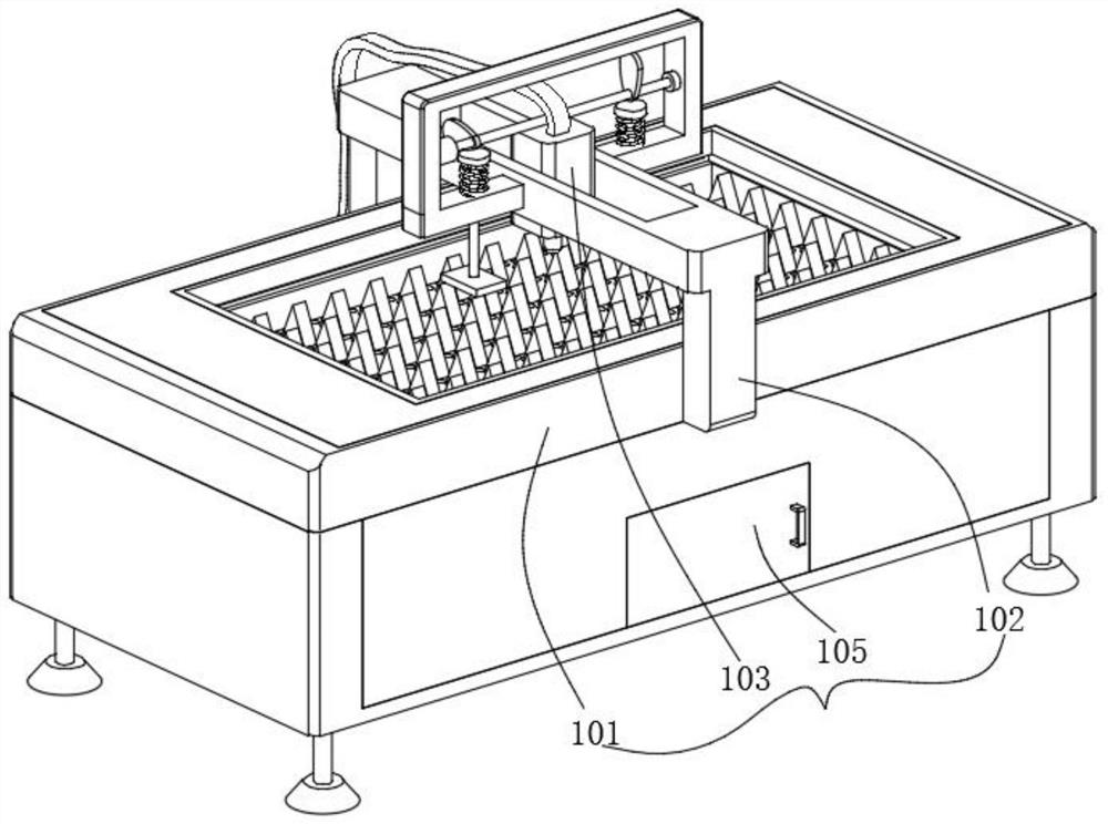
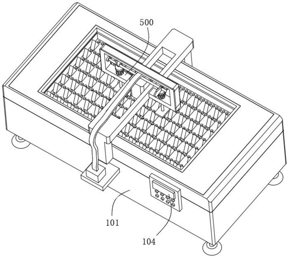
[0047] to combine figure 1 , 2 , 3, 4 and 5, the laser cutting machine for precious metal processing provided by the present invention includes a laser cutting machine body 100, a cleaning mechanism 200, a shaking mechanism 300, a collection mechanism 400 and a positioning mechanism 500, and the laser cutting machine body 100 includes a processing Table 101, the connecting frame 102 arranged on the processing table 101, the machine head 103 arranged on the connecting frame 102 and a plurality of through holes provided on the processing table 101, the processing table 101 has a built-in first cavity and a second cavity body, the cleaning mechanism 200 includes a first motor 201 fixed in the first cavity, a screw 202 fixed to the output end of the first motor 201, a slide bar fixed on one side of the first cavity, suitable for the opposite screw 202 and The equipment box sliding on the slide bar, the connecting rod in the equipment box can be installed rotatably, the rack 204 f...

Embodiment 2

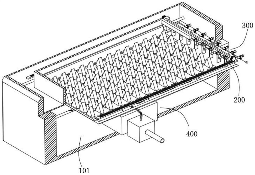
[0050] to combine image 3 and 6 As shown, on the basis of Embodiment 1, the shaking mechanism 300 includes a second motor 301 fixed in the first cavity, a rotating shaft fixed at the output end of the second motor 301, a plurality of worms 303 arranged on the rotating shaft, and Rotate a plurality of rotating shafts installed on the inner wall of the first cavity, the worm wheel 302 that is fitted on the rotating shaft and meshed with the worm 303 for transmission, and the transmission plate 304 fixed on the rotating shaft, the second motor 301 starts to drive the rotating shaft to rotate, and the worm 303 rotates with the rotating shaft, and the worm screw 303 and the worm wheel 302 are meshed for transmission. The worm screw 303 drives the rotating shaft to rotate through the worm wheel 302, and the transmission plate 304 rotates with the rotating shaft, and then the soft brush 205 can be cleaned, and the soft brush can be cleaned. The powder contaminated on the 205 is cle...

Embodiment 3

[0053] to combine image 3 and 7 As shown, in the above embodiment, the collection mechanism 400 includes a hopper 401 fixed in the second cavity and a collection box arranged at the bottom of the hopper 401. The hopper 401 is located below the through hole, and the falling precious metal powder falls into the Into the guide hopper 401, and then into the collection box, the powder can be gathered together, which is convenient for the staff to take the powder away.

[0054] Specifically, the collection mechanism 400 also includes a fan 407 fixed in the second cavity, a guide box 405 arranged in the guide hopper 401 and connected to the fan 407 through a pipeline, and stoppers fixed on both sides of the guide box 405. block, a plurality of guide tubes 406 fixed on the guide box 405, and a filter cover fixed on the guide tube 406, the end of the limit block is slidably connected with the inner wall of the guide hopper 401 through a chute, and the fan 407 starts The wind is used...


PUM


Abstract

The invention discloses a laser cutting machine for precious metal machining. The cutting machine comprises a laser cutting machine body, a cleaning mechanism, a shaking mechanism, a collecting mechanism and a positioning mechanism, wherein the laser cutting machine body comprises a machining table, a connecting frame arranged on the machining table, a machine head arranged on the connecting frame and a plurality of through holes formed in the machining table; a first cavity and a second cavity are formed in the machining table, and the cleaning mechanism comprises a first motor fixedly installed in the first cavity, a connecting rod rotatably installed in the equipment box, racks fixedly connected to two sides of the first cavity, a second gear arranged on a transmission shaft in a sleeving mode and in meshing transmission with a toothed plate and a banister brush fixedly connected to the bottom of the transmission shaft. The shaking mechanism is located on one side of the cleaning mechanism and used for cleaning precious metal powder on the banister brush, the collecting mechanism is located in the second cavity and used for collecting powder cleaned by the cleaning mechanism, and the positioning mechanism is located on the connecting frame and used for positioning workpieces machined by the laser cutting machine body.

Description

technical field [0001] The invention relates to the technical field of precious metals, in particular to a laser cutting machine for precious metal processing. Background technique [0002] Precious metals mainly refer to gold, silver and platinum group metals (ruthenium, rhodium, palladium, osmium, iridium, platinum) and other 8 metal elements. Most of these metals have beautiful colors and are quite resistant to chemicals. Precious metal jewelry includes various hair accessories, jewelry, earrings, neck ornaments, hand ornaments, foot ornaments, clothing, etc. [0003] When processing precious metals, it is necessary to cut the precious metals into the desired shape. Using laser cutting, the cutting precision is high and the cutting surface is smooth. However, when the existing laser cutting machine cuts the workpiece, the workpiece will be damaged. Powder, while precious metals are of high value, it is difficult to clean the workbench manually, and it is not easy to coll...

Claims


Application Information

Patent Timeline
Patent Type & Authority Applications(China)
IPC IPC(8): B23K26/38B23K26/70B23K26/142
CPCB23K26/38B23K26/702B23K26/142
Inventor 王勇
Owner JIANGSU HUYUN LASER EQUIP CO LTD
Why Eureka
Try Eureka