Micro thermocouple threading device and machining method

A thermocouple wire and thermocouple technology, applied in metal processing, metal processing equipment, manufacturing tools, etc., can solve the problems of low quality thermocouple products, low work efficiency, high work intensity, etc.

Pending Publication Date: 2021-09-14
HUAZHONG UNIV OF SCI & TECH
View PDF4 Cites 1 Cited by
  • Summary
  • Abstract
  • Description
  • Claims
  • Application Information

AI Technical Summary

Problems solved by technology

[0004] Aiming at the above defects or improvement needs of the prior art, the present invention provides a micro-thermocouple threading device and a processing method, thereby solving the problem of low quality of thermocouple products caused by manual threading of U-shaped quartz long tubes in the prior art, Technical problems of low work efficiency and high work intensity

Method used


Image

  • Micro thermocouple threading device and machining method
  • Micro thermocouple threading device and machining method
  • Micro thermocouple threading device and machining method

Examples


Embodiment 1

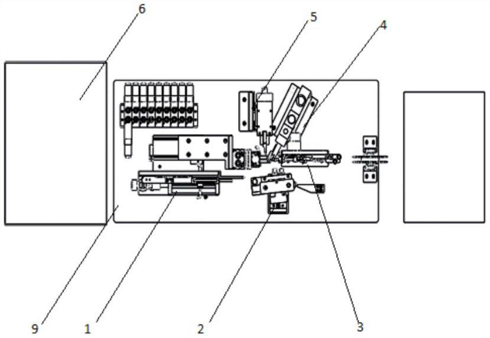
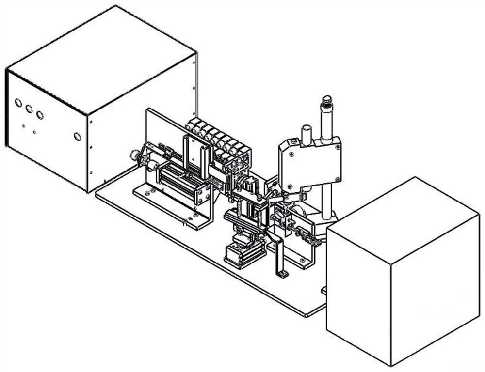
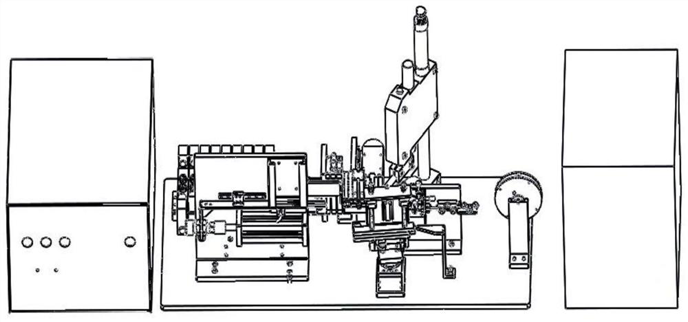
[0065] This embodiment provides a processing method for a thermocouple wire threading device, including a storage and feeding mechanism 1, a thermocouple wire clamping mechanism 2, a wire feeding mechanism 3, a welding mechanism 4, a shearing mechanism 5, a control box 6 and a processing platform 9 , specifically including the following steps:

[0066] S100, place the U-shaped quartz long tube in the material storage mechanism 11, draw out the drawing wire from the drawing wire reel 33, and place it at the initial position of the wire feeding mechanism 3; check the power status of the equipment with a pneumatic power switch; the operator will Adjust the control box 6 knob to automatic mode and step on the foot switch, put the thermocouple wire into the thermocouple wire clamping mechanism 2 with tweezers, release the foot pedal to clamp the thermocouple wire after the comparison is completed.

[0067] S200, the pusher 121 pushes the U-shaped quartz long tube into the clamper 1...

Embodiment 2

[0076] This embodiment provides a processing method for a thermocouple wire threading device, including a storage and feeding mechanism 1, a wire feeding mechanism 3, a welding mechanism 4, a shearing mechanism 5, a control box 6 and a processing platform 9, and also includes two different The thermocouple sending welding mechanism of the thermocouple wire welding specifically includes the following steps:

[0077] S100, place the U-shaped long quartz tube in the material storage mechanism 11, draw out the drawing wire from the drawing wire tray, and place it at the starting position of the wire feeding mechanism 3; turn on the power switch, and check the power-on state of the equipment.

[0078] S200, the operator adjusts the 6 knob of the control box to the automatic mode and steps on the foot switch, the thermocouple sending and welding mechanism welds two different thermocouples, cuts, the robotic arm clamps the thermocouple, and detects the quality of the solder joints. A...


PUM


Abstract

The invention discloses a micro thermocouple threading device and a machining method, and belongs to the technical field of thermocouple manufacturing. The micro thermocouple threading device comprises a material storing and feeding mechanism, a thermocouple wire clamping mechanism, a wire feeding mechanism, a welding mechanism, a shearing mechanism and a machining platform, wherein the material storing and feeding mechanism conveys a U-shaped quartz long tube to a threading area above the machining platform; the wire feeding mechanism enables a traction wire to penetrate through the U-shaped quartz long tube and conveys the traction wire to a welding area above the machining platform; the thermocouple wire clamping mechanism is used for clamping a thermocouple wire and conveying the thermocouple wire after length comparison to the welding area above the machining platform to form lap joint with the thermocouple wire in the welding area; the welding mechanism is used for welding the thermocouple wire and the traction wire in the welding area; and the shearing mechanism shears off the redundant traction wire after the welded thermocouple wire and the traction wire move to the designated position, and therefore threading work is completed. Manual errors can be reduced, the threading efficiency is greatly improved, the production cycle of thermocouple products is shortened, and the labor intensity of operators is reduced.

Description

technical field [0001] The invention belongs to the technical field of thermocouple manufacture, and more specifically relates to a fine thermocouple wire threading device and a processing method. Background technique [0002] Thermocouple is a commonly used temperature measuring element in temperature measuring instruments. Thermocouple is widely used. It has many advantages such as simple structure, convenient manufacture, good interchangeability, wide measurement range, high precision, small inertia and easy remote transmission of output signal. It has a wide range of applications in various fields of national economic development. It welds two thermocouple wires of different materials together, and the two ends are interconnected. When the temperature at the two nodes is different, a thermoelectric potential will be generated at the node, that is, the temperature signal is converted into a thermoelectric potential signal, which is passed through the electrical instrument...

Claims


Application Information

Patent Timeline
IPC IPC(8): B23P19/04B23K31/02B21F11/00
CPCB23P19/04B23P19/001B23P19/006B23K31/02B21F11/00
Inventor 吴丰顺黄坤龙含孝
Owner HUAZHONG UNIV OF SCI & TECH
Why Eureka
Try Eureka