Special dustproof polymethyl methacrylate polishing machine

A polishing machine and acrylic technology, applied in the field of mechanical processing, can solve the problems of human injury and the inability of the polishing disc to adjust itself, and achieve the effects of being conducive to cleaning, good surface sealing, and convenient for hand-held

Inactive Publication Date: 2021-09-17
JIANGSU TOMSON NEW MATERIAL TECH CO LTD
View PDF0 Cites 0 Cited by
  • Summary
  • Abstract
  • Description
  • Claims
  • Application Information

AI Technical Summary

Problems solved by technology

[0004] The object of the present invention is to provide a special acrylic dust-proof polishing machine, which solves the following technical problems: (1) By setting a protective shell on the outer periphery of the polishing disc, it prevents the splashing of the polishing liquid during the polishing process, effectively controlling dust and polishing The splash of the liquid, at the same time, the protective cotton is added to the outer ring of the polishing disc, and the contact with the inner surface of the protective shell will not cause scratches, and the surface is well sealed, which solves the technical problem of human injury caused by dust and polishing liquid splashes during polishing in the prior art ; (2) When the polishing disc touches the uneven workpiece surface, the polishing disc is squeezed by the workpiece surface. When the pressure is greater than the elastic force of the telescopic spring, the rotating shaft drives the telescopic ring to move to one side, squeezing the telescopic spring, and the joint bearing Under the action of the universal floating of the rotating shaft and the self-regulation of the polishing disc, it solves the technical problem that the polishing disc cannot be self-adjusted during polishing in the prior art, and avoids the friction between the polishing disc and the rotating shaft caused by the hard contact between the polishing disc and the workpiece. damage, improving the efficiency and quality of workpiece polishing, telescopic springs and joint bearings realize the universal floating and reset of the rotating shaft, and the dust cover at the end of the fixing groove can seal the inside of the fixing sleeve in a dust-proof manner; (3) The fixed shell is placed between the two U-shaped clamps, and the rotating handle is rotated. The rotating handle drives the threaded column to rotate, and the rotation of the threaded column drives the two U-shaped clamps to slide relatively in the sliding groove at the bottom of the fixing seat, and then drives the two U-shaped clamps. The U-shaped clips are inserted into the slots on both sides of the fixed shell, and the U-shaped clamps are locked in the slots through the fixing bolts. The fixed shell and the fixed assembly are designed separately, which is easy to disassemble and easy to clean. The fixed shell is separated from the fixed assembly. After the top is removed, the fixed handle on one side of the protective shell can be conveniently held by the personnel to start the driving motor, the output shaft of the driving motor drives the driving bevel gear to rotate, the driving bevel gear meshes with the driven bevel gear to drive the rotating shaft to rotate, and the rotating shaft passes through the coupling The device drives the fixed sleeve to rotate, the fixed sleeve rotates to drive the joint bearing in the fixed groove to rotate, and then drives the rotating shaft to rotate, and the rotating shaft rotates to drive the polishing disc at the end of the rotating shaft to rotate, and the staff can perform manual polishing, which is highly functional

Method used


Image

  • Special dustproof polymethyl methacrylate polishing machine
  • Special dustproof polymethyl methacrylate polishing machine
  • Special dustproof polymethyl methacrylate polishing machine

Examples


Embodiment Construction

[0029] The following will clearly and completely describe the technical solutions in the embodiments of the present invention with reference to the accompanying drawings in the embodiments of the present invention. Obviously, the described embodiments are only some, not all, embodiments of the present invention. Based on the embodiments of the present invention, all other embodiments obtained by persons of ordinary skill in the art without creative efforts fall within the protection scope of the present invention.

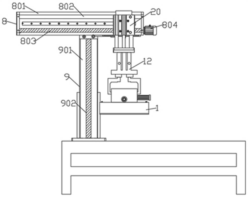
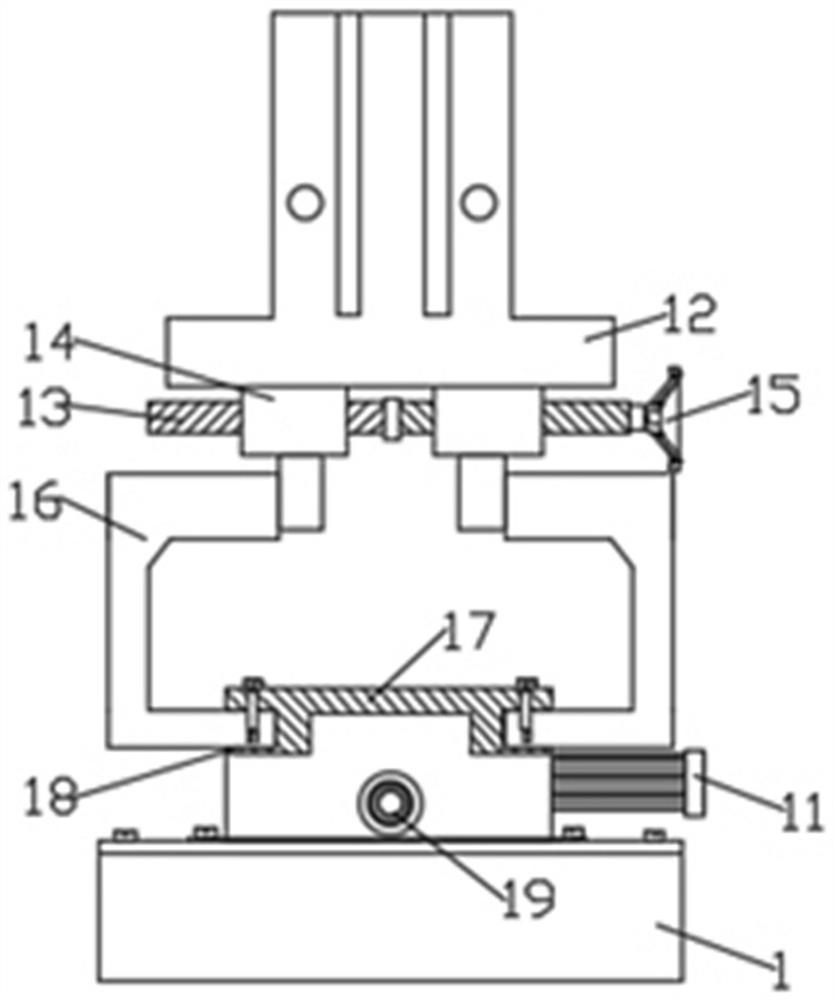
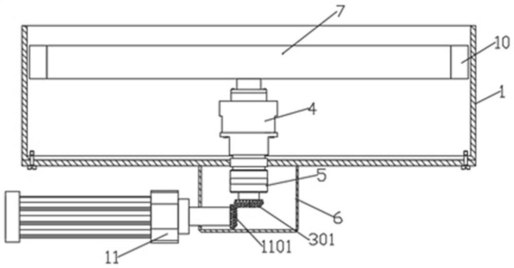
[0030] see Figure 1-5 As shown, the present invention is a special acrylic dust-proof polishing machine, a special acrylic dust-proof polishing machine, including a shell, the shell includes a protective shell 1 and a top plate 2, and the top of the protective shell 1 is provided with a top plate 2 , the top plate 2 is fixedly installed on the top of the protective shell 1 by fixing bolts, the center of the top plate 2 is provided with a fixing hole 201, the prote...


PUM


Abstract

The invention discloses a special dustproof polymethyl methacrylate polishing machine which comprises a shell. The shell comprises a protective shell and a top plate, the top plate is arranged at the top of the protective shell and fixedly installed at the top of the protective shell through fixing bolts, a fixing hole is formed in the center of the top plate, a polishing disc is arranged in the protective shell, a rotating assembly is arranged on the polishing disc and comprises a fixing sleeve, a fixing groove is formed in the fixing sleeve, a knuckle bearing is fixedly installed in the fixing groove, the knuckle bearing is arranged on a rotating shaft in a sleeving mode, and the end, away from the fixing groove, of the rotating shaft is fixedly installed at the top of the polishing disc. According to the special dustproof polymethyl methacrylate polishing machine provided by the invention, the protective shell is arranged on the periphery of the polishing disc, so that splashing of polishing liquid in the polishing process is prevented, and splashing of dust and the polishing liquid is effectively controlled; meanwhile, protective cotton is additionally arranged on an outer ring of the polishing disc, so that scratching is avoided when the protective cotton makes contact with the inner face of the protective shell; and the technical problem that in the prior art, during polishing, the dust and the polishing liquid splash to cause harm to a human body is solved.

Description

technical field [0001] The invention relates to the technical field of mechanical processing, in particular to an acrylic dust-proof special polishing machine. Background technique [0002] The polishing machine is an electric tool, generally composed of basic components such as a base, a throwing disc, a polishing fabric, a polishing cover and a cover. The ring is fastened on the polishing disc, and after the motor is turned on and started through the switch on the base, the sample can be polished by hand to exert pressure on the rotating polishing disc. [0003] The function of polishing is mainly to reduce the surface roughness of the workpiece to obtain a bright and smooth surface, that is, it is a modification process on the surface of the workpiece by using polishing tools and abrasive particles or other polishing media. In the traditional polishing process, the staff uses a hand-held polishing wheel to perform grinding work on the surface of the parts to be processed...

Claims


Application Information

Patent Timeline
Patent Type & Authority Applications(China)
IPC IPC(8): B24B29/02B24B55/06B24B55/04B24B55/00B24B27/00B24B23/02B24B27/02B24B47/06
CPCB24B29/02B24B55/06B24B55/04B24B55/00B24B27/0046B24B23/02B24B27/02B24B47/06
Inventor 汤月生张高峰肖建霞汤佳晨成伟
Owner JIANGSU TOMSON NEW MATERIAL TECH CO LTD
Why Eureka
Try Eureka