

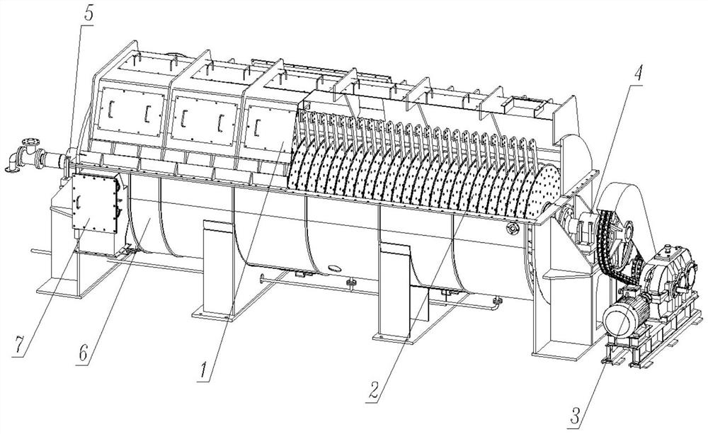
Split type disc sludge drying machine
A sludge drying and split-type technology, which is applied in the directions of dehydration/drying/concentrated sludge treatment, separation methods, and separation of dispersed particles, which can solve the problem that the hollow paddle sludge dryer occupies a large area and increases sludge treatment Manufacturers' equipment costs, high requirements for plant auxiliary facilities, etc., to achieve the effect of reducing transportation costs and labor costs, saving manufacturing costs, and facilitating overall hoisting
- Summary
- Abstract
- Description
- Claims
- Application Information
AI Technical Summary
Problems solved by technology
Method used
Image

Examples
Embodiment Construction
[0038] The present invention will be further described below in conjunction with specific examples, but the present invention is not limited to these specific implementations. Those skilled in the art will realize that the present invention covers all alternatives, modifications and equivalents as may be included within the scope of the claims.
[0039]In describing the present invention, it should be understood that the terms "center", "longitudinal", "transverse", "length", "width", "thickness", "upper", "lower", "front", " The orientations or positional relationships indicated by "rear", "left", "right", "vertical", "horizontal", "top", "bottom", "inner", "clockwise", "counterclockwise" are based on the attached The orientation or positional relationship shown in the figure is only for the convenience of describing the present invention and simplifying the description, and does not indicate or imply that the referred device or element must have a specific orientation, be co...
PUM
 Abstract
Description
Claims
Application Information