Main case shell and positioning tool

A technology for positioning tooling and main box, applied in the direction of instruments, electrical digital data processing, digital data processing parts, etc., can solve the problems of dislocation and offset of multiple plates, difficult to meet the accuracy, structural strength decline, etc., to achieve the connection accuracy High, reduce stress deformation, improve the effect of structural strength

Pending Publication Date: 2021-09-17
SHENZHEN KONCOIL TECH
View PDF0 Cites 0 Cited by
  • Summary
  • Abstract
  • Description
  • Claims
  • Application Information

AI Technical Summary

Problems solved by technology

[0003] Most of the main box shells in the related art are assembled with multiple boards and a frame for supporting the boards. Since the processing of the frame and the boards belongs to different processes, the error after the assembly and splicing is relatively large, resulting in The accuracy is difficult to meet the use in the field of medical devices; in addition, most of its assembly methods use simple screw splicing and assembly. During the screw splicing process, multiple different boards and frames are fixed by screw splicing. Screws can only clamp part of the boards so that the integrity of multiple boards is not high, and screwing too tight will also cause misalignment and offset between multiple boards, making the assembled structure The intensity will decrease to some extent

Method used


Image

  • Main case shell and positioning tool
  • Main case shell and positioning tool
  • Main case shell and positioning tool

Examples


Embodiment 1

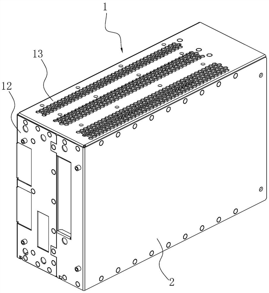
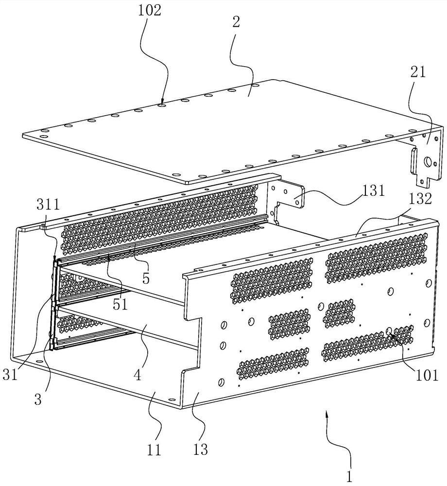
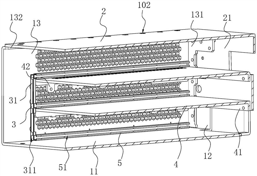
[0040] Refer figure 1with figure 2 The main box housing includes the body plate 1 and the side plate 2, and the body plate 1 includes a main board 11, a rear panel 12, and two side plates 13. The main board 11, the rear plate 12, and the two side plates 13 are all integrally formed, and the rear panel 12 and the side plate 13 are folded toward the same side and both are perpendicular to the main board 11, and the side plate 13 is bent towards the side edge of the rear panel 12. The slair portion 131 is formed, and the side plate 13 of the two side plates 13 is bent toward, and the rear panel 12 abuts against the abutment portion 131 near the side plate 13, the rear panel 12 and the abutment portion 131 can use the screw Secure or pull the rivetable mode, at this time, since the rear panel 12 and the abutting portion 131 are bent by one of the entire molded plates, the two screws are fixed or rivetically fixed, and the two do not disorderly. Thus, the fixed accuracy is relatively h...

Embodiment 2

[0054] The difference between the embodiment and the first embodiment is that

[0055] Refer Image 6 with Figure 7 The positioning plate 6 is also provided with a card attachment assembly 7, and the lock assembly 7 includes a restricting plate 71 and a buckle hook 72, and the restricting plate 71 is provided with two restriction plates 71 and the positioning plate 6 integrally formed, two restrictions. The plates 71 are respectively disposed on both sides of the positioning plate 6, and the restricting plate 71 and the seating profile of the positioning plate 6 are U-shaped in the width direction.

[0056] Refer Figure 7 with Figure 8 The hook 72 is made of a high molecular resin to reduce the hook 72 to scratch the edge plate 13, the fastening section 72 includes a strip structure and includes a connecting portion 721 and a fastener 722, a connecting portion 721 and a buckle The connecting portion 722 is integrated, and the connecting portion 721 is fixedly coupled to one side su...


PUM


Abstract

The invention relates to a maincase shell and a positioning tool, and relates to the technical field of main case shell machining. The main case shell comprises a main body plate frame and side plates, the main body plate frame comprises a main plate, a rear plate and two side plates, the rear plate and the side plates are formed by folding the main plate, the side edges, facing the rear plate, of the side plates are bent to form abutting parts used for supporting the rear plate, the abutting portion is connected to the rear plate, the side edge, away from the main plate, of the side plate is bent to form a landing edge, the side plate is connected to the landing edge in a riveting mode, and the side plate and the main plate frame define a box structure with an opening in one side. The main case shell has the effect that the structural strength of the main caseshell is higher under certain precision.

Description

Technical field [0001] The present application relates to the technical field of host case shell processing, in particular, involving a host case and positioning tool. Background technique [0002] With the rapid development of electronic technology, the main chassis of the integrated circuit motherboard is applied in various fields, and the size of the main box housing will also make adaptation changes with different fields of application. In particular, in the field of medical devices, the host box housing requires higher precision and structural strength, and also needs a more compact structure, which is adapted to other components of the medical device. [0003] The main box shell of the related art uses multiple plates and assembly of the frame assembly for supporting the plate. Since the process of the frame and the plate body belongs to different processes, the error is relatively large after assembly splicing, resulting in It is difficult to meet the use of the field of m...

Claims


Application Information

Patent Timeline
Patent Type & Authority Applications(China)
IPC IPC(8): G06F1/18
CPCG06F1/181G06F1/183
Inventor 王小锋章代红张勇厉晓明
Owner SHENZHEN KONCOIL TECH
Why Eureka
Try Eureka