A grinding equipment for hardware lock processing
A hardware lock and equipment technology, which is applied in the direction of metal processing equipment, grinding/polishing equipment, workpiece feed movement control, etc., can solve the problems of low production efficiency, staff injury, harmful dust, etc., to improve efficiency, Damage reduction, high degree of automation effect
- Summary
- Abstract
- Description
- Claims
- Application Information
AI Technical Summary
Problems solved by technology
Method used
Image

Examples
Embodiment 1
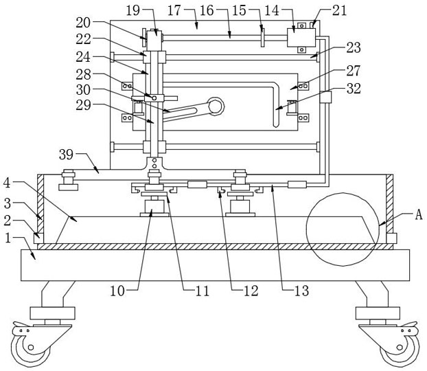
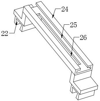
[0034] Example 1, please refer to Figure 1-9 In the embodiment of the present invention, a grinding apparatus for hardware lock processing, including a base plate 1, and a protective case 3 and a support plate 17 are fixed to the base plate 1, and the protective case 3 is fixedly installed and supported. Platform 4, the support platform 4 is mounted with a grinding assembly for polishing the lock body, the support plate 17, fixedly mounted, sliding on the sliding block 22, two sets of sliding The guide plate 24 is mounted between the block 22, and the guide plate 24 is opened on the guide plate 24, and the sliding groove 25 is slidably mounted with a lifting bar 29, and one end of the ridge 29 is fixedly mounted 39 The mounting frame 39 is mounted with a clamp assembly for fastening the lock body, the support plate 17, and a transposition assembly for driving the lifting rod 29 is also mounted.
[0035]During the production of lock production, by the set base plate 1, the base pla...
Embodiment 2
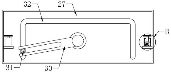
[0036] Embodiment 2, on the basis of the first example, the transposition assembly includes a movable slot 26, a modulating plate 27, a drive rod 30, a sliding column 31, a guide groove 32, and a drive motor 33, and the modulator 27 fixed Installed on the support plate 17, a guide groove 32 is opened on the adjustment plate 27, and the guide groove 32 is slidably mounted with a sliding post 31, and the sliding post 31 is connected to the roses 29. The moving slot 26 is opened on the guide plate 24, and the sliding post 31 is slidably coupled to one end of the drive rod 30, and the other end of the drive rod 30 is fixed to the output of the drive motor 33, said The drive motor 33 is fixedly mounted on the support plate 17.
[0037] When the position of the lock body is required, the driving motor 33 is started, and the driving rod 30 can be rotated, wherein the open slot is opened on the drive rod 30, and generates power by the slide on the sliding column 31. The action can drive t...
Embodiment 3
[0038] Example 3. On the basis of the second embodiment, the support platform 4 is a hollow tetra-edge structure, and the height of the support platform 4 is smaller than the height of the protective case 3, and the bottom circumferential direction is uniformly distributed in the bottom of the protective case 3. A plurality of slaglets are mounted, the cross section of the slide rail 23 is a trapezoidal structure, and the number of rails 23 is two sets, and the sliding groove 25 is a T-shaped structure.
[0039] By the set of protective case 3 and the support platform 4, since the support platform 4 is located within the protective case 3, and the height of the support platform 4 can be worn, the part of the dust is blocked, and the environmental pollution is lowered. At the same time, Since the support platform 4 uses a four-priced structure, the ground slag can be dropped into the protective case 3 under the action of gravity, and can be cleaned up by the staff by the set slide ...
PUM
 Abstract
Description
Claims
Application Information