Free-form surface construction method for laser beam shaping

A construction method and laser beam technology, applied in optics, optical components, instruments, etc., can solve problems such as material overheating, damage, normal vector deviation of data sampling points, etc., and achieve the effect of uniform energy distribution

Active Publication Date: 2021-09-21
白 洁
View PDF3 Cites 0 Cited by
  • Summary
  • Abstract
  • Description
  • Claims
  • Application Information

AI Technical Summary

Problems solved by technology

In the process of laser application, due to the uneven energy distribution of the laser beam, it may cause local overheating and damage to the material. In order to avoid the above situation, the laser beam must be shaped
At present, typical laser beam shaping technologies include aspheric lens group shaping, microlens array shaping, diffractive optical element shaping, birefringent lens group shaping and liquid crystal spatial light modulator, etc. Compared with the above-mentioned laser beam shaping technology, free-form surface beam Shaping technology can realize the control of beam intensity distribution and phase distribution at the same time, but the free-form surface design method has the problem of deviation of the normal vector of the data sampling point during the iterative expansion of the initial curve, which makes the beam shaping effect poor

Method used


Image

  • Free-form surface construction method for laser beam shaping
  • Free-form surface construction method for laser beam shaping
  • Free-form surface construction method for laser beam shaping

Examples


Embodiment Construction

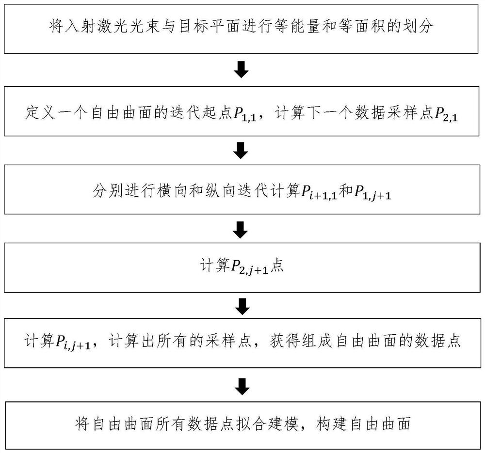
[0071] like figure 1 , a free-form surface construction method for laser beam shaping described in this embodiment, the flow chart is as follows figure 1 shown, including:

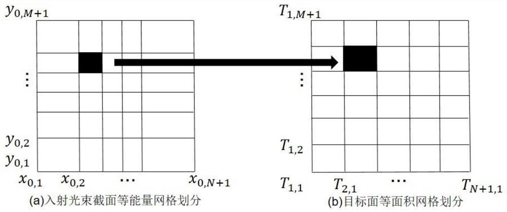
[0072] (1) Divide the collimated laser beam into equal energy divisions on the beam waist section, divide the target plane into equal areas, and construct the corresponding relationship between the collimated laser beam and the target plane according to the marginal ray theory and energy mapping relationship, as shown in figure 2 shown.

[0073] A collimated beam with a rectangular aperture is used, and the equal energy is divided into N×M parts on the beam waist section, and the equal area of ​​the target plane is divided into N×M parts.

[0074] The expression of Gaussian distribution of collimated laser beam irradiance is:

[0075]

[0076] In the formula, r is the distance from the center point of the optical axis, w 0 is the beam waist width of the laser beam, the luminous intensity of the col...


PUM


Abstract

The invention discloses a free-form surface construction method for laser beam shaping. The method comprises the steps of: carrying out equal-energy division on a collimated laser beam, carrying out equal-area division on a target plane, and constructing a corresponding relation between the collimated laser beam and the target plane; defining an initial point P1, 1 on a free-form surface reflector, and iteratively calculating the position of a next data sampling point P2, 1 along the longitudinal direction; obtaining a recursive expression of a longitudinal curve data sampling point Pi + 1, 1 and a recursive expression of a transverse direction data sampling point P1, j + 1, and calculating the position of a free-form surface bidirectional initial curve data sampling point; acquiring the position of a free-form surface data sampling point P2, j + 1; calculating the position of a data sampling point Pi, j + 1, and calculating the positions of all data sampling points forming the free-form surface; and performing fitting modeling on all the free-form surface data sampling points to construct a free-form surface. The free-form surface can efficiently shape the collimated incident laser beam into a square uniform beam, an ideal effect can be obtained just through one-time ray tracing, and secondary optimization is not needed.

Description

technical field [0001] The invention relates to laser beam shaping technology, in particular to a free-form surface construction method for laser beam shaping. Background technique [0002] Because of its many advantages such as coherence, monochromaticity, good directionality and high brightness, laser is widely used in lithography, material processing and biomedicine. During the laser application process, due to the uneven energy distribution of the laser beam, the material may be locally overheated and damaged. In order to avoid the above situation, the laser beam must be shaped. At present, typical laser beam shaping technologies include aspheric lens group shaping, microlens array shaping, diffractive optical element shaping, birefringent lens group shaping and liquid crystal spatial light modulator, etc. Compared with the above-mentioned laser beam shaping technology, free-form surface beam Shaping technology can control the beam intensity distribution and phase distr...

Claims


Application Information

Patent Timeline
Patent Type & Authority Applications(China)
IPC IPC(8): G02B27/00G02B27/09
CPCG02B27/0012G02B27/0938
Inventor 詹浣湫叶井飞孙奇杨砚超陈柯宇杨明珠曹兆楼郑改革
Owner 白 洁
Why Eureka
Try Eureka