Method and system for correcting asynchronous sampling time sequences between channels

A technology of sampling timing and correction method, applied in transmission systems, electrical components, transmitter monitoring and other directions, can solve the problems of complex process, relatively high sampling rate requirements, unable to correctly solve the channel delay, etc., to achieve simple hardware, expand The effect of universal scope

Active Publication Date: 2021-09-21
SOUTHWEST CHINA RES INST OF ELECTRONICS EQUIP
View PDF6 Cites 1 Cited by
  • Summary
  • Abstract
  • Description
  • Claims
  • Application Information

AI Technical Summary

Problems solved by technology

The delay correction in the 
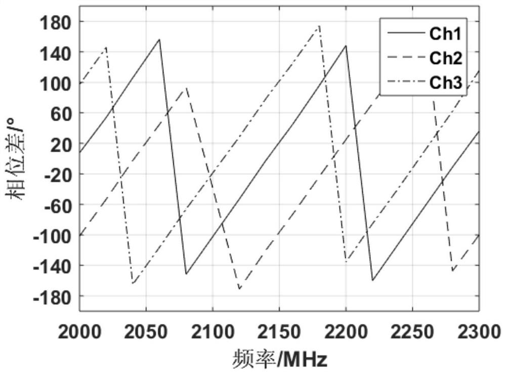
frequency domain calculates the delay through the phase difference. The phase difference calculation method is ambiguous in the calculated phase difference because of the periodicity of the trigonometric function, so that the range of the corrected delay can only be limited to one signal cycle; The delay calculation in the time domain is to calculate the phase difference through the signal expression, and to calculate the delay through the phase difference, so calculation errors will be introduced
[0004]The traditional 
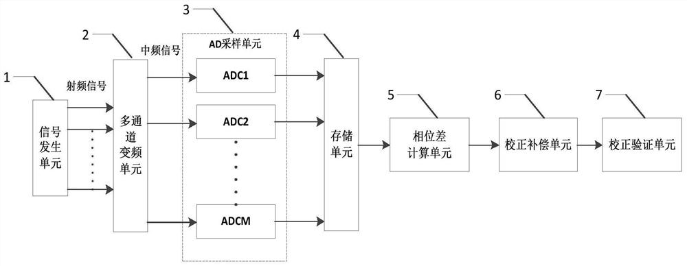
processing method is to calculate the phase difference between channels at a single frequency point, and calculate the time between channels according to the relationship between phase difference and frequency delay, and correct and compensate the corresponding channels. The published literature mainly includes: "Phase Difference Method Corrects Multi-Channel AD Acquisition High-precision Time Error" in "Electronic World", extracts the phase difference and then calculates the synchronization time through the principle of arcsine transformation Error, due to the periodicity of the sine function, the calculated phase difference is ambiguous. Therefore, the calculation principle of arcsine determines that it can only calculate the sampling delay within a single signal period. For delays greater than one signal period, its The method will fail; the "Phase Difference Accurate Measurement Method Applicable to Asynchronous Sampling" in "Power Grid Technology", the phase difference measurement method based on the correlation analysis method, also has the periodic problem of the sinusoidal function, and is based on the existence of voltage and current It is carried out under the premise of transformers, and its application range is very limited due to high hardware requirements; "Design and Implementation of Multi-channel Synchronous Data Acquisition System" in "University of Electronic Science and Technology", calculates the time delay between channels through the DFT algorithm, There is also the ambiguity problem of the phase difference, and the sampling frequency must be an integer multiple of the signal frequency; the "Sine Wave Fitting Method to Evaluate the Inter-channel Delay of the Data Acquisition System" in the "Journal of Testing Technology" uses an oscilloscope to observe the inter-channel waveform Rising edge delay, naked eye observation, the error is relatively large; "Information and Computer (Theoretical Edition)" "Synchronization Time Difference and Phase Difference Analysis Caused by Small Phase Difference Calculation" calculates the phase difference through the theoretical formula of the time domain, and introduces the calculation error, and engineering practice requires multi-stage filters to filter out redundant calculation items; "Phase Difference Measurement Method and Error Analysis Based on Digital Orthogonal Transformation" in "Journal of Circuits and Systems" requires that the sampling frequency be an integer multiple of the signal frequency, and the same There is a problem of phase difference ambiguity and calculation errors are introduced; "PhaseMeasurement and Adjustment of Digital Signals Using Random SamplingTechnique" of "IEEE International Symposium on Circuits and Systems" improves the relative phase accuracy through random sampling statistical techniques, but it needs to design complex hardware circuit
[0005]The calculation on the time domain waveform requires a relatively high sampling rate, and there are errors caused by the calculation; the phase difference calculation in the frequency domain has the problem of phase difference ambiguity, which leads to When correcting a channel with a delay greater than one signal cycle, the channel delay cannot be solved correctly; using an oscilloscope to observe the waveform delay in the time domain, the delay accuracy cannot be guaranteed
These methods can directly or indirectly calculate the time delay of sampling out-of-sync between channels, but the process is relatively complicated, the requirements for hardware design are relatively high, and the correction method is relatively poor in versatility and has great limitations.

Method used


Image

  • Method and system for correcting asynchronous sampling time sequences between channels
  • Method and system for correcting asynchronous sampling time sequences between channels
  • Method and system for correcting asynchronous sampling time sequences between channels

Examples


Embodiment Construction

[0030] The present invention will be further described below in conjunction with the accompanying drawings.

[0031] Such as figure 1As shown, the present invention provides a correction system for asynchronous sampling timing between channels, including a signal generation unit, a multi-channel frequency conversion unit, an AD sampling unit, a storage unit, a phase difference calculation unit, a correction compensation unit and a correction verification unit. The signal generation unit outputs the RF signal of the specified frequency to the power splitter, and the power splitter outputs M channels to the multi-channel frequency conversion unit; the multi-channel frequency conversion unit converts the radio frequency signal into an intermediate frequency signal; the AD sampling unit collects the intermediate frequency after M channel frequency conversion The data of the signal; the storage unit stores the AD data of the intermediate frequency signals of different frequencies c...


PUM


Abstract

The invention provides a method for correcting asynchronous sampling time sequences between channels, which comprises the following steps of: S1, setting a radio frequency signal with a specified frequency, outputting M radio frequency signals and converting the M radio frequency signals into intermediate frequency signals; S2, acquiring and storing the M intermediate frequency signals through an AD sampling unit, repeating the S1 to S2 to sample and store the AD data of the intermediate frequency signals of multiple frequencies; S3, calculating the phase difference between the collected and stored AD data of other channels and that in the reference channel under all frequencies, drawing a phase difference curve that the phase difference changes along with the frequency, and drawing a real phase difference change trend curve at the same time; S4, determining channels with asynchronous sampling according to the phase difference curve, and performing corresponding correction on the asynchronous channels; and S5, verifying the corrected channels. The invention aims to quickly correct the delay inequality of asynchronous sampling time sequences of cross-signal periods among multiple channels without introducing calculation errors, hardware required by a correction system is simple, the synchronous debugging efficiency is greatly improved, and the universality range of the correction method is expanded.

Description

technical field [0001] The invention relates to the field of wideband digital sampling, in particular to a method and system for correcting sampling time sequence asynchrony between channels. Background technique [0002] In the modern digital beamforming system, the number of array antennas is large, corresponding to the large number of sampling channels of the array antennas. For this reason, multiple acquisition boards are generally designed on the hardware for parallel sampling processing, but at the same time there is a problem of synchronization between acquisition boards. It includes synchronization across clock domains between boards and synchronization of sampling timing within a board, so it becomes difficult to debug system sampling timing synchronization. [0003] Under existing conditions, correction methods for delay calculation in frequency domain and time domain are relatively common. The delay correction in the frequency domain calculates the delay through ...

Claims


Application Information

Patent Timeline
IPC IPC(8): H04B17/12H04B17/21H04B1/00
CPCH04B17/12H04B17/21H04B1/0007
Inventor 张慧君谢伟谭瑞捷吕彤光刘承禹魏建功王岩肖龙李超何超卿浩博冯帆彭胜
Owner SOUTHWEST CHINA RES INST OF ELECTRONICS EQUIP
Why Eureka
Try Eureka