Filtering type strong transient electromagnetic pulse protection structure
A technology of electromagnetic pulse and protective structure, applied in the direction of electrical components, magnetic field/electric field shielding, transmission system, etc., can solve the problem that the slow response speed of the slow edge module cannot suppress the strong electromagnetic pulse of the fast edge in time, and affect the normal operation and independence of the wireless transceiver system. Problems such as inconvenient application of functional modules, to achieve the effect of solving the problem of import dependence, compact structure and good sealing
- Summary
- Abstract
- Description
- Claims
- Application Information
AI Technical Summary
Problems solved by technology
Method used
Image

Examples
Embodiment Construction
[0035] The present invention will be described in detail below in conjunction with the accompanying drawings and embodiments.
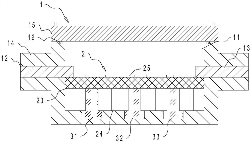
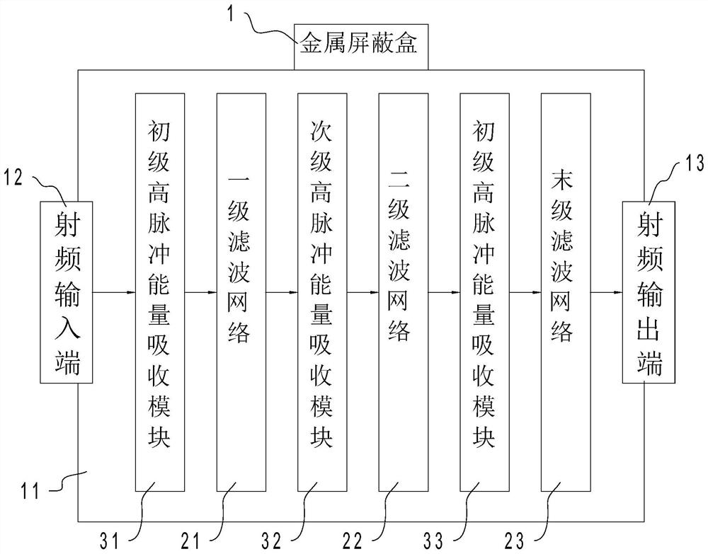
[0036]At present, in the protection of strong transient electromagnetic pulses, the narrowband radio frequency link protection technology of microsecond level (us) slow frontier (hereinafter referred to as "slow edge") strong electromagnetic pulse (such as lightning electromagnetic pulse) is relatively mature, while for other types of Nanosecond (ns) and below fast frontier (hereinafter referred to as "fast edge") strong electromagnetic pulse protection technology is still in its infancy. Fast edge and slow edge protection are usually independent functional modules, which makes the application inconvenient. The fast edge protection module cannot bear The energy of the slow-edge strong pulse, the response speed of the slow-edge module is very slow and cannot suppress the fast-edge strong electromagnetic pulse in time; at the same time, adding a special ...
PUM
 Abstract
Description
Claims
Application Information
 - R&D
- Intellectual Property
- Life Sciences
- Materials
- Tech Scout
- Unparalleled Data Quality
- Higher Quality Content
- 60% Fewer Hallucinations
Browse by: Latest US Patents, China's latest patents, Technical Efficacy Thesaurus, Application Domain, Technology Topic, Popular Technical Reports.
© 2025 PatSnap. All rights reserved.Legal|Privacy policy|Modern Slavery Act Transparency Statement|Sitemap|About US| Contact US: help@patsnap.com