Shield machine

A technology of shield machine and host system, applied in the field of shield machine, can solve the problems of limiting the applicability and flexibility of the shield machine, difficult work of the shield machine, shortening the design and manufacturing period and manufacturing cost, etc. The effect of construction requirements, enhanced flexibility, and reduction of processing and manufacturing costs

Active Publication Date: 2022-03-04
CHINA RAILWAY ENGINEERING EQUIPMENT GROUP CO LTD
View PDF10 Cites 0 Cited by
  • Summary
  • Abstract
  • Description
  • Claims
  • Application Information

AI Technical Summary

Problems solved by technology

However, the conventional form of shield machine at home and abroad is a huge and complex complete set of excavation and lining equipment in terms of the length of the whole machine (main machine + supporting system) and the weight of the whole machine. It costs hundreds of tons, and the manufacturing cost is tens of millions of yuan. These factors ultimately make it difficult to complete a series of tasks such as the design, manufacture, assembly, commissioning, starting and excavation of the shield machine in a short period of time. Usually, the entire tunnel It takes at least one year to complete the breakthrough, which limits the applicability and flexibility of the shield machine to a certain extent
[0003] It is difficult to successfully complete the task with conventional shield machines for tunnel projects with harsh external conditions such as tight construction schedules, difficulty in starting the whole machine, and strict cost control. In view of this situation, it is necessary to design a flexible shield machine Machine, this shield machine gets rid of the equipment arrangement and construction method of the conventional shield machine, can realize the rapid production and manufacture of the shield machine, greatly shorten the design and manufacture period and manufacturing cost, economical and efficient construction excavation, suitable for short mileage , Small-diameter tunnel projects with tight schedules

Method used


Image

  • Shield machine
  • Shield machine
  • Shield machine

Examples


Embodiment Construction

[0044] In order to have a clearer understanding of the technical solutions, objectives and effects of the present invention, the specific implementation manners of the present invention will now be described with reference to the accompanying drawings. Among them, the terms "first", "second" and so on are only used for descriptive purposes, and cannot be understood as indicating or implying relative importance or implicitly specifying the number of indicated technical features. Therefore, "first" is limited to , "second", etc. may expressly or implicitly include one or more of these features. In the description of the present invention, unless otherwise specified, "plurality" means two or more.

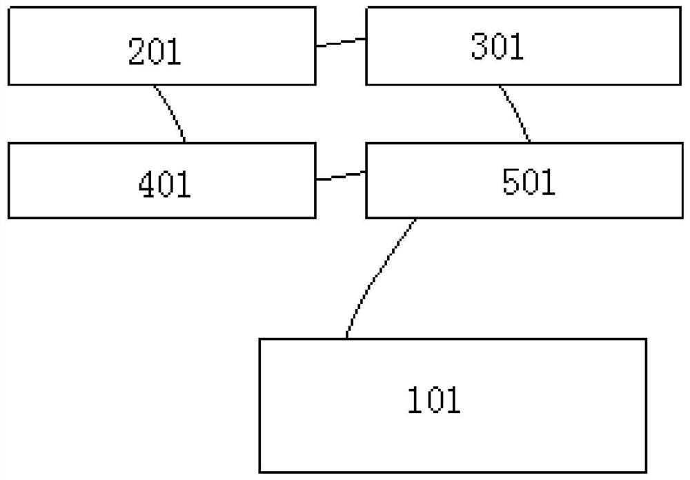
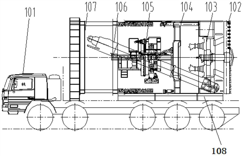
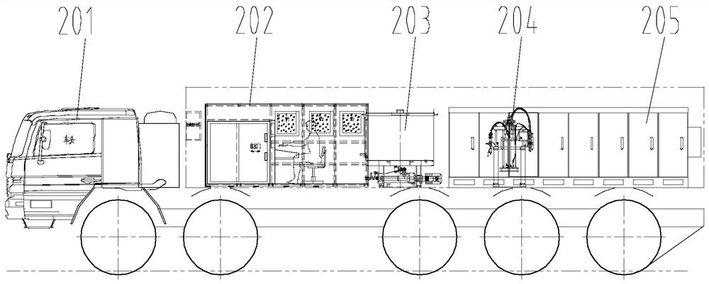
[0045] Such as figure 1 As shown, the present invention provides a shield machine, which is suitable for small-diameter tunnel projects with short mileage and tight construction period. The shield machine includes a first heavy-duty truck 101, a second heavy-duty truck 201, and a thi...


PUM


Abstract

The invention provides a shield machine, which includes a first heavy truck, a second heavy truck, a third heavy truck, a fourth heavy truck and a fifth heavy truck, the first heavy truck is provided with a reaction force frame and a main engine system, the reaction frame is connected with the host system and can drive the host system to move; the second heavy truck is equipped with a control system; the third heavy truck is equipped with a hydraulic system; the fourth heavy truck is equipped with an injection system; the fifth heavy truck is equipped with an injection system; The heavy truck is provided with a power supply system; wherein, the power supply system can be electrically connected with the control system, the control system can be electrically connected with the hydraulic system and the injection system, and the control system can control the actions of the hydraulic system and the injection system. The shield machine of the present invention occupies a small space, is convenient for production, manufacturing and assembly, does not need to configure a production workshop with complex functions, can start excavation at any time, enhances the flexibility of the shield machine, and effectively reduces processing and manufacturing costs and assembly and debugging time.

Description

technical field [0001] The invention relates to the technical field of tunnel construction control, in particular to a shield machine. Background technique [0002] In the current tunnel construction, the shield machine has gradually been widely used due to its advantages of high degree of automation, high construction safety and low pollution. However, the conventional form of shield machine at home and abroad is a huge and complex complete set of excavation and lining equipment in terms of the length of the whole machine (main machine + supporting system) and the weight of the whole machine. It costs hundreds of tons, and the manufacturing cost is tens of millions of yuan. These factors ultimately make it difficult to complete a series of tasks such as the design, manufacture, assembly, commissioning, starting and excavation of the shield machine in a short period of time. Usually, the entire tunnel It takes at least one year to complete the breakthrough, which limits the...

Claims


Application Information

Patent Timeline
Patent Type & Authority Patents(China)
IPC IPC(8): E21D9/087E21D9/093E21D9/12E21D11/04E21D11/08E21D11/40
CPCE21D9/0873E21D9/12E21D9/124E21D9/093E21D11/08E21D11/04E21D11/40
Inventor 贾连辉胡燕伟阴书玉龚廷民郭沛霖徐金秋张永辉
Owner CHINA RAILWAY ENGINEERING EQUIPMENT GROUP CO LTD
Why Eureka
Try Eureka