Manufacturing method of high-light-concentration high-resolution variable-conical-surface bent crystal

A manufacturing method and high-resolution technology, applied in the analysis of materials, material analysis using wave/particle radiation, measuring devices, etc., can solve the problems of limited detection, small conical curvature radius, and long position, and improve the surface shape Precision, high light collection efficiency, and compactness

Active Publication Date: 2021-09-28
四川欧瑞特光电科技有限公司
View PDF18 Cites 0 Cited by
  • Summary
  • Abstract
  • Description
  • Claims
  • Application Information

AI Technical Summary

Problems solved by technology

The position of the recording surface of such a geometric optical path is too long and it is not convenient to connect with time-resolved equipment, and the radius of curvature of the cone is required to be small, which is difficult to meet in actual operation.
In addition, if the light source is not on the axis of the cone, the simple cone structure has its obvious disadvantages, such as large aberrations, theoretically only one point is aberration-free focusing, and the detection spectral range is relatively narrow
[0007] When the crystal is cylindrical, the detection surface of the cylindrical crystal spectrometer can only be at the central axis of the cylinder, and the detection is limited

Method used


Image

  • Manufacturing method of high-light-concentration high-resolution variable-conical-surface bent crystal
  • Manufacturing method of high-light-concentration high-resolution variable-conical-surface bent crystal
  • Manufacturing method of high-light-concentration high-resolution variable-conical-surface bent crystal

Examples


Embodiment 1

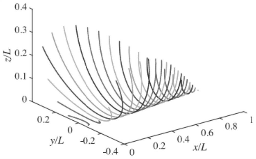
[0041] The method of modeling in step S1 is: use each theoretical circular arc as the contour line, X-axis and three guiding lines on both sides of the X-axis to form a surface, and draw the corresponding circular arc at each coordinate point of the X-axis, Make two endpoints of each arc at the Z coordinate, respectively connect each endpoint of the arc at the two endpoints on the Z coordinate, and make two splines to complete the modeling.

[0042] For example:

[0043] Take X coordinates: 253.00, 253.01, 253.02, 253.03...313.00;

[0044] Take the Z coordinates: -30, +30;

[0045] At each coordinate point of the X axis, draw the corresponding arc lines, draw the two end points of each arc when the Z coordinates are -30 and 30, and connect the arcs at Z=-30 and Z=30 respectively At the end point, make two splines, the two splines and the X-axis are used as the guide line when forming a surface, and the reflection surface is composed of the guide line and the contour lines of...

Embodiment 2

[0047] The method for three-coordinate machine measurement in step S4 is: the XYZ coordinates of the measurement points are generated earlier before the three-coordinate measurement, the numerical control processing module of the three-dimensional software is used to generate the NC program, and the established three-dimensional model is used to set the distance of the measurement point, the spherical measurement point First, use the processing module to generate the NC processing program. After running the program, the coordinates of the starting point of tool processing on the program are the XYZ theoretical coordinates of the point required by the measurement surface shape. Use these coordinate values ​​as the three coordinates to set the position of the measuring point, and get the theoretical The surface shape difference between the Z coordinate and the measured Z coordinate;

[0048]For example, when using UG software, the method is as follows: use the established 3D mode...

Embodiment 3

[0050] In step S6, the method of adopting high-precision surface shape to keep the positioning pressing block molding and shaping includes: after the substrate and the wafer are cleaned, the substrate is fixed on the workbench, and ultraviolet glue is coated on it. Gently place the wafer on the glue, and align the positioning block and lightly compact it to remove air bubbles. Press a weight of appropriate weight on it, keep it fixed, and bake it with a UV lamp for more than 24 hours. Take it out and clean it and leave it for later. test.

[0051] When gluing the wafer with the base, in order to ensure the surface shape accuracy of the curved crystal, under the condition that the base surface shape accuracy is appropriate, this embodiment adopts the method of high-precision surface shape holding and positioning pressing block molding and shaping, and uses the high-precision surface shape to keep the positioning. The surface shape of the briquetting block is used to ensure the ...


PUM


Abstract

The invention discloses a manufacturing method of a high-light-concentration high-resolution variable-conical-surface bent crystal, belongs to the technical field of optical crystal manufacturing, and solves the problems that a simple conical surface has theoretical phase aberration and a detection surface of a cylindrical crystal spectrometer can only be located at the position of a central axis of a cylindrical surface. The manufacturing method comprises the following steps: S1, modeling: modeling by adopting three-dimensional software; S2, wafer manufacturing: directionally cutting the alpha quartz crystal wafer by using an X-ray direction finder, polishing a first surface, and polishing a second surface after polishing; S3, bending a crystal substrate: processing by adopting a quartz material; S4, measuring surface precision: using a three-coordinate machine with the precision of 1 [mu]m for measurement; S5, manufacturing a surface type keeping and positioning pressing block: manufacturing a standard pressing block which is the same as the bent crystal in external dimension, the same as the bent crystal in reflecting surface type and opposite in concave-convex by using a quartz material; and S6, sizing and gluing, wherein the curved crystal face type after gluing is completed is completed through the face type of the face type maintaining and positioning pressing block. The remeasurement precision of the manufactured variable-conical-surface bent crystal is less than or equal to 5 [mu]m, and the precision is high.

Description

technical field [0001] The invention belongs to the technical field of optical crystal manufacture, and in particular relates to a method for manufacturing a curved crystal with variable cone surface and high light collection and high resolution. Background technique [0002] X-ray crystal spectrometer is an X-ray spectrometer that uses crystals as spectrometers. The crystal has appropriate lattice intervals, which can diffract X-rays of a certain wavelength, and can play a role similar to that of a diffraction grating in an optical analytical instrument. It works as follows: [0003] The interaction between the laser and the plasma produces X-rays that irradiate the crystal, and after the crystal is diffracted and split, the spatial intensity distribution is formed on the recording surface (X-ray CCD or X-ray CMOS). X-rays are diffracted by crystals to satisfy the Bragg diffraction equation: [0004] 2d sin Θ = m λ (m = 0, 1, 2, ...) [0005] where d is the interplanar ...

Claims


Application Information

Patent Timeline
Patent Type & Authority Applications(China)
IPC IPC(8): G01N23/2202G01N23/223
CPCG01N23/2202G01N23/223
Inventor 王峰尚万里杨国洪范朦蒋毅杨龙范松如王玉鲁罗荣荣
Owner 四川欧瑞特光电科技有限公司
Why Eureka
Try Eureka