
Equipment for glue production water treatment process and use method thereof

A treatment process and water production technology, applied in water/sludge/sewage treatment, natural water treatment, dehydration/drying/concentrated sludge treatment, etc., can solve the problem of low dehydration efficiency

Active Publication Date: 2021-10-01
浙江华硕科技股份有限公司
View PDF8 Cites 0 Cited by
  • Summary
  • Abstract
  • Description
  • Claims
  • Application Information

AI Technical Summary

Problems solved by technology

[0004] However, when the screw-stack sludge dewatering machine is used to separate solid impurities in sewage, the motor needs to rotate at a relatively low speed, resulting in the low dewatering efficiency of the screw-stack sludge dewatering machine

Method used


Image

  • Equipment for glue production water treatment process and use method thereof
  • Equipment for glue production water treatment process and use method thereof
  • Equipment for glue production water treatment process and use method thereof

Examples


Embodiment 1

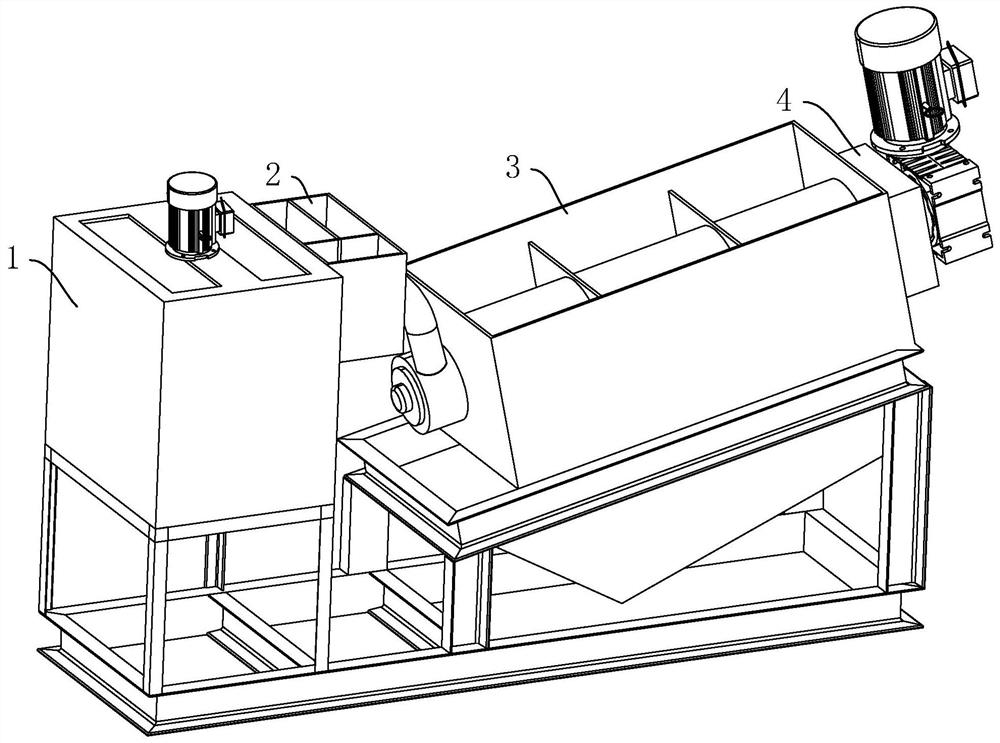
[0041] A glue production water treatment process equipment, such as figure 1 As shown, it includes a mixing tank 1 and a stacked screw filter press. When in use, the raw water and the flocculant are poured into the mixing tank 1 . The mixing tank 1 fully stirs the raw water and the flocculant, so that the particles in the raw water are fully combined. After that, the material inside the mixing tank 1 is injected into the screw filter press. The screw press filter presses the material, so that the water and the combined relay are separated to meet the national discharge requirements.

[0042] The stacked screw filter press includes a mud feeding box 2 , a casing 3 and a mud discharging box 4 arranged in sequence. When in use, the water in the raw water is discharged from the shell 3, and the particles combined in the raw water are discharged from the sludge discharge box 4.

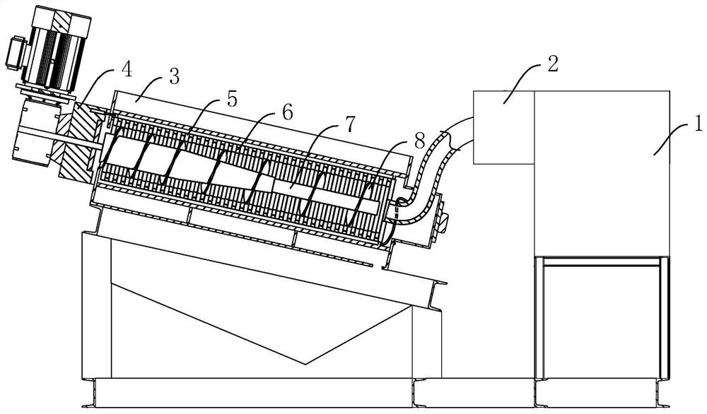
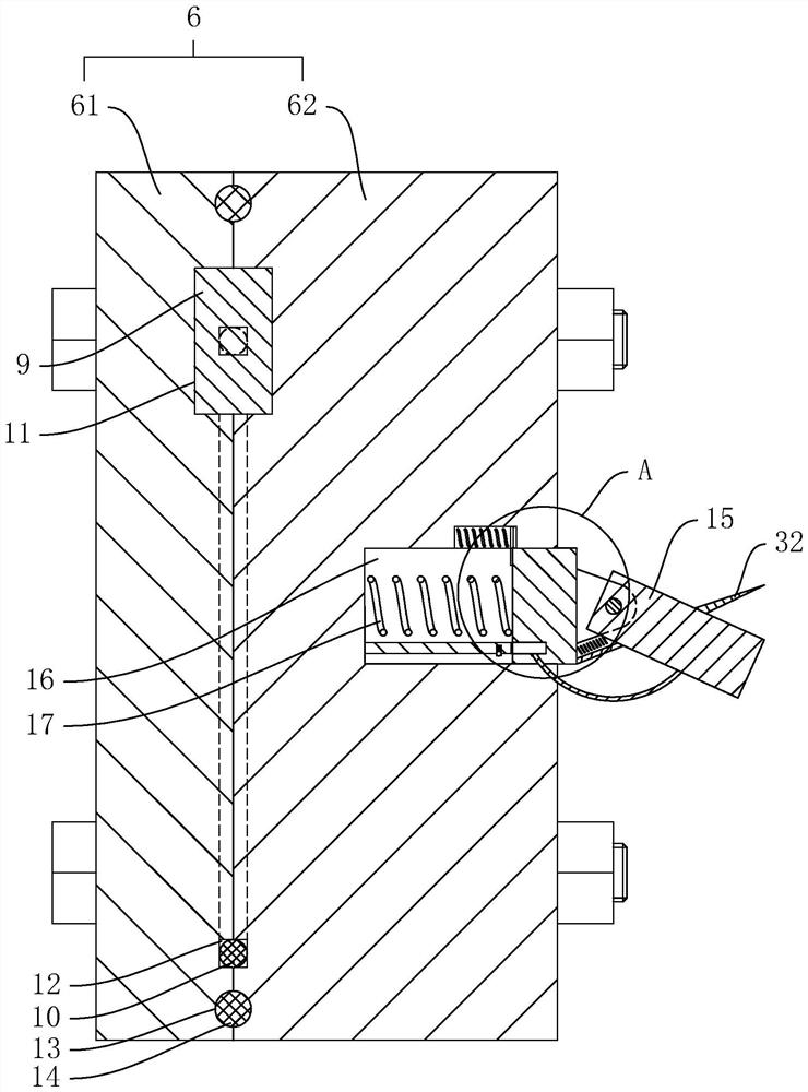
[0043] like figure 2 As shown, the housing 3 is provided with a fixed plate 5 and a movable plate...

Embodiment 2

[0053] A method of using the equipment for the production of water treatment technology for glue as described in Embodiment 1, comprising the steps of:

[0054] The first step: inject the raw water of mass M into the mixing tank;

[0055] The second step: add 0.25%M-0.35%M polyacrylamide into the mixing barrel;

[0056] The third step: add ferric chloride solution with a concentration of 0.2%M-0.4%M as 20% to the mixing barrel;

[0057] The fourth step: use the mixing bucket to stir for 5 minutes, so that some impurities in the raw water can be flocculated;

[0058] The fifth step: add flake alkali or sulfuric acid to the mixing barrel, and adjust the pH to 6-8;

[0059] Step 6: Let stand for 3 minutes;

[0060] The seventh step: add 0.25%M-0.5%M polyaluminum chloride to the mixing barrel;

[0061] The eighth step: use the mixing bucket to stir for 5 minutes, so that some impurities in the raw water can be flocculated;

[0062] The ninth step: inject the material in the m...


PUM


Abstract

The invention provides equipment for a glue production water treatment process and a use method thereof. The equipment comprises a stirring barrel and a stacked screw type filter press, and the stacked screw type filter press comprises a sludge feeding box, a shell and a sludge discharging box which are arranged in sequence; a fixed plate and a movable plate are arranged in the shell at an interval, a spiral shaft is rotationally connected to the shell, a spiral piece is arranged on the peripheral wall of the spiral shaft, and the spiral piece abuts against the inner ring of the movable plate; and a power supply and an electric heating wire are embedded in the movable plate, the electric heating wire is arranged in the circumferential direction of the movable plate, and the two ends of the electric heating wire are connected with the positive electrode and the negative electrode of the power supply correspondingly. The power supply supplies power to the electric heating wire, and the electric heating wire heats the movable plate to accelerate water evaporation, so that impurities can be dried more quickly, and the equipment for the glue production water treatment process can have higher dehydration efficiency. In the rotating process of the spiral piece, the spiral piece can push the movable plate to move between the two fixed plates so that part of impurities attached to the fixed plates can be removed.

Description

technical field [0001] The present invention relates to the production waste water treatment of glue, in particular, to a kind of equipment for the production water treatment process of glue and its use method. Background technique [0002] At present, the Chinese patent with the publication number CN201525798U discloses a screw-stacked sludge dewatering machine, which includes a casing, a fixed plate, a movable plate, a screw shaft, a screw blade, an adjustment block and a screw. Two sides of the shell are respectively provided with a mud feeding box and a mud discharging box. The fixed plate and the movable plate are arranged inside the casing at intervals, and the fixed plate and the movable plate are arranged concentrically. The screw shaft passes through the center of the fixed plate and the movable plate, the screw piece is fixedly connected to the outer peripheral wall of the screw shaft, and the pitch of the screw piece gradually decreases from the side of the mud f...

Claims


Application Information

Patent Timeline
IPC IPC(8): C02F11/125C02F11/13C02F11/14C02F11/147C02F11/143C02F103/34
CPCC02F11/125C02F11/13C02F11/14C02F11/147C02F11/143C02F2103/34
Inventor 潘增华潘军行
Owner 浙江华硕科技股份有限公司
Learn More