Quenching equipment for gear machining and quenching process of quenching equipment

A quenching equipment and gear technology, applied in the field of gear processing, can solve the problems of long quenching time, unstable gear quenching degree, unstable gear quality, etc., and achieve the effect of high quality, high toughness and stable quality

Inactive Publication Date: 2021-10-01
黄林枢
View PDF8 Cites 2 Cited by
  • Summary
  • Abstract
  • Description
  • Claims
  • Application Information

AI Technical Summary

Problems solved by technology

[0005] The purpose of the present invention is to provide a quenching equipment and quenching process for gear processing, to solve the above-mentioned background technology proposed in the gear quenching process, as the temperature rises, its hardness rises, and the gear quenching needs to reduce the gear The surface hardness is improved, and the hardness of the inner core of the gear is kept unchanged as much as possible to improve the overall performance of the gear; however, the existing traditional technology basically controls the degree of quenching by a fixed time during quenching, and it is impossible to ensure that the surface of the gear reaches the predetermined temperature. Immediate cooling, which makes the degree of quenching of the gear unstable, which in turn makes the quality of the gear unstable, or the quenching time is slightly longer. Due to the thermal conductivity of the gear itself, the temperature of the inner core of the gear is higher, and the hardness of the inner core is relatively hard, or The quenching time is slightly short, the gear surface temperature is not enough, and the gear surface hardness is not enough

Method used


Image

  • Quenching equipment for gear machining and quenching process of quenching equipment
  • Quenching equipment for gear machining and quenching process of quenching equipment
  • Quenching equipment for gear machining and quenching process of quenching equipment

Examples


Embodiment Construction

[0043] The following will clearly and completely describe the technical solutions in the embodiments of the present invention with reference to the accompanying drawings in the embodiments of the present invention. Obviously, the described embodiments are only some, not all, embodiments of the present invention. Based on the embodiments of the present invention, all other embodiments obtained by persons of ordinary skill in the art without creative efforts fall within the protection scope of the present invention.

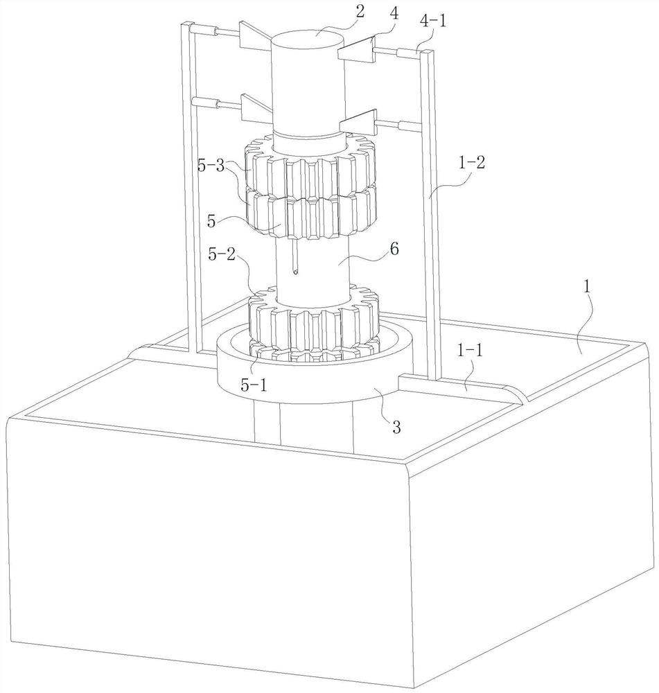
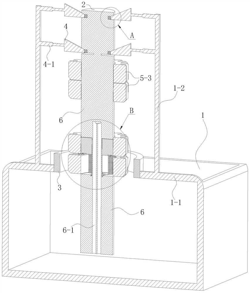
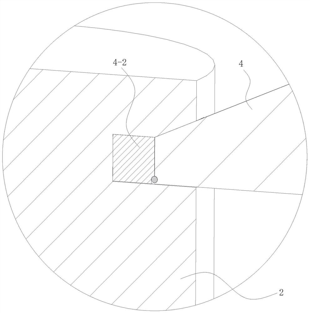
[0044] see Figure 1-12 , the present invention provides a technical solution: a quenching equipment for gear processing, including a cooling pool 1, a high-frequency magnetic induction heater 3, a gear 5 and a rotating shaft 6, characterized in that it also includes a fixed shaft 2, a wedge-shaped Support plate 4, electromagnet 7, annular limit rod 8, sliding column 9 and limit connecting rod 10; the high-frequency magnetic induction heater 3 is fixedly installed ...


PUM


Abstract

The invention discloses quenching equipment for gear machining in the technical field of gear machining. The quenching equipment comprises a cooling pond, a high-frequency magnetic induction heater, gears and a rotating shaft, and is characterized by further comprising a fixed shaft, wedge-shaped supporting plates, an electromagnet, an annular limiting rod, a sliding column and a limiting connecting rod; the high-frequency magnetic induction heater is fixedly installed at the upper end of the cooling pond, the four wedge-shaped supporting plates are vertically distributed in pairs and symmetrically arranged above the high-frequency magnetic induction heater relative to the axis of the high-frequency magnetic induction heater, the wedge-shaped supporting plates are all connected with the fixed shaft in a clamped mode, and the fixed shaft and the high-frequency magnetic induction heater are coaxial; the lower end of the rotating shaft is rotationally mounted at the lower end of the fixed shaft, and the multiple gears sleeve the rotating shaft; and the wedge-shaped supporting plates, the electromagnet, the annular limiting rod, the sliding column and the limiting connecting rod are all mounted on the rotating shaft and used for controlling the positions of the gears on the rotating shaft. Compared with a conventional method for controlling the quenching degree through time, the quenching time is controlled through the quenching degree, so that the quality of the gears is stable, and the quality is high.

Description

technical field [0001] The invention relates to the technical field of gear processing, in particular to a quenching device for gear processing and a quenching process thereof. Background technique [0002] The principle of gear quenching: the workpiece is placed in the inductor, and the inductor is generally a hollow copper tube that inputs intermediate frequency or high frequency alternating current (1000-300000Hz or higher). An alternating magnetic field is generated to generate an induced current of the same frequency in the workpiece. The distribution of this induced current in the workpiece is uneven, strong on the surface, but weak inside, and close to 0 in the center, using this skin effect , can rapidly heat the surface of the workpiece, and the surface temperature rises to 800-1000°C in a few seconds, while the core temperature rises very little. [0003] During the gear quenching process, as the temperature rises, the hardness increases accordingly, and the gear ...

Claims


Application Information

Patent Timeline
Patent Type & Authority Applications(China)
IPC IPC(8): C21D9/32C21D1/10C21D1/63C21D1/18
CPCC21D9/32C21D1/10C21D1/63C21D1/18Y02P10/25
Inventor 黄林枢
Owner 黄林枢
Why Eureka
Try Eureka