
Holographic antenna, control method, computer device and storage medium

A holographic antenna and computer program technology, applied in the direction of antennas, antenna arrays, antenna arrays powered independently, etc., can solve the problems of high cost, cumbersome manufacturing process, complex structure, etc., and achieve the effect of low cost, simple structure, and easy processing

Active Publication Date: 2022-01-11
SOUTH CHINA UNIV OF TECH +1
View PDF6 Cites 0 Cited by
  • Summary
  • Abstract
  • Description
  • Claims
  • Application Information

AI Technical Summary

Problems solved by technology

Although the phased array antenna has the ability to control the beam scanning, since the phased array antenna is composed of many arrays, these arrays usually include oscillators, slots, etc., and each array is usually controlled separately, resulting in its internal structure. Complicated, making its manufacturing process cumbersome and costly

Method used


Image

  • Holographic antenna, control method, computer device and storage medium
  • Holographic antenna, control method, computer device and storage medium
  • Holographic antenna, control method, computer device and storage medium

Examples


example 2

[0069] Example 2, the second dielectric board includes a first surface and a second surface, and the control circuit 12 may be loaded on the second surface of the second dielectric board.

[0070] It should be noted that the second dielectric plate can be a rectangular plate with the same size as the first metal plate 1 , or a rectangular plate with the same area as the slit array 8 . The first surface of the first metal plate 1 is attached to the second surface of the second dielectric plate.

[0071] Optionally, the radio frequency switch 11 may be a PIN diode or a varactor. It can be understood that a PIN diode is loaded on the control circuit 12 of each slot in the slot array 8. When the positive and negative poles of the PIN diode are applied with a reverse bias voltage, the PIN diode is in a cut-off state, the coupling path is disconnected, and the slot can radiate A quasi-TEM wave is emitted; when a forward bias voltage is applied to the positive and negative poles of ...


PUM


Abstract

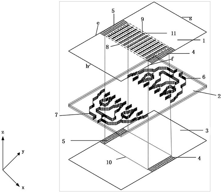
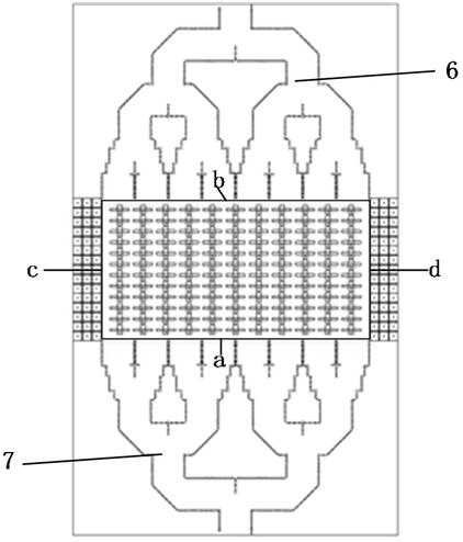
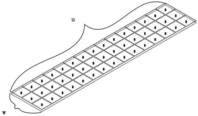
The present application relates to a holographic antenna, a control method, a computer device and a storage medium. The holographic antenna includes a first dielectric plate and a first metal plate and a second metal plate attached to its first surface and second surface respectively; a symmetrical first electromagnetic band gap array and a second electromagnetic band gap array on each of the above plates The gap arrays form the first artificial magnetic surface and the second artificial magnetic surface respectively; the first power divider and the second power divider integrated on the first dielectric board, the first artificial magnetic surface and the second artificial magnetic surface are on the first A cavity structure is formed between the metal plate and the second metal plate; the first metal plate is provided with a slot array on one side of the cavity structure. The first artificial magnetic surface and the second artificial magnetic surface are used to convert the TE waves generated by the first power divider and the second power divider between the first metal plate and the second metal plate into quasi-TEM waves in the cavity structure . The slot array is used to control the radiation of quasi-TEM waves inside the cavity structure. Using the holographic antenna can reduce the complexity of the antenna structure.

Description

technical field [0001] The present application relates to the technical field of direct current transmission, in particular to a holographic antenna, a control method, computer equipment and a storage medium. Background technique [0002] Antenna is an important part of a wireless communication system, and its main function is to transmit and receive wireless signals. With the rapid development of modern wireless communication technology, the requirements for the performance of the antenna itself are getting higher and higher, which is specifically reflected in the higher and higher requirements for the directivity of the antenna beam, such as the ability to realize beam scanning. [0003] In the prior art, the most common array antenna is a phased array antenna. Although the phased array antenna has beam scanning control capability, since the phased array antenna is composed of many arrays, these arrays usually include oscillators, slots, etc., and each array is usually co...

Claims


Application Information

Patent Timeline
Patent Type & Authority Patents(China)
IPC IPC(8): H01Q21/06H01Q21/00
CPCH01Q21/064H01Q21/0006
Inventor 章秀银姚逸慧苏华峰周哲杨波伍尚坤高霞高永振
Owner SOUTH CHINA UNIV OF TECH
Learn More