Ferrite particles, electrophotographic developer carrier core material, electrophotographic developer carrier, and electrophotographic developer

An electrophotography and ferrite technology, applied in the direction of developer, iron oxide/hydroxide, circuit, etc., can solve the problems of easy white spots, carrier scattering, etc., and achieve the effect of inhibiting carrier scattering and high strength

Pending Publication Date: 2021-10-01
POWDERTECH
View PDF4 Cites 0 Cited by
  • Summary
  • Abstract
  • Description
  • Claims
  • Application Information

AI Technical Summary

Problems solved by technology

However, if the particle size of the carrier is reduced, carrier scattering tends to occur, and image defects such as white spots tend to occur

Method used


Image

  • Ferrite particles, electrophotographic developer carrier core material, electrophotographic developer carrier, and electrophotographic developer
  • Ferrite particles, electrophotographic developer carrier core material, electrophotographic developer carrier, and electrophotographic developer
  • Ferrite particles, electrophotographic developer carrier core material, electrophotographic developer carrier, and electrophotographic developer

Examples


Embodiment 1

[0168] (1) Ferrite particles

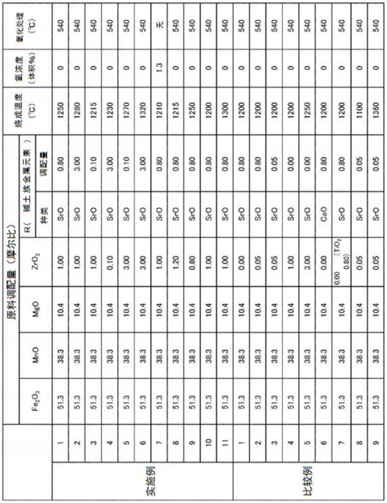
[0169] In Example 1, it was produced as follows so that from (MnO)x(MgO)y(Fe 2 o 3 ) The crystal phase composition composed of spinel crystals represented by the chemical formula of z as the main component contains SrZrO 3 The chemical formula (R = Sr) represented by the perovskite crystal phase composition of ferrite particles composed of crystal phase. First, the MnO raw material, the MgO raw material, and the Fe 2 o 3 Raw materials, in terms of molar ratio, MnO conversion: 38.3, MgO conversion: 10.4, Fe 2 o 3 : 51.3. In addition, the SrO raw material was weighed so that it would be SrO: 0.8 with respect to the main component raw material: 100 in molar ratio. Here, trimanganese tetraoxide was used as the MnO raw material, magnesium oxide was used as the MgO raw material, and Fe 2 o 3 Iron oxide was used as the raw material, and strontium carbonate was used as the SrO raw material.

[0170] Then, the weighed raw material was pulverized...

Embodiment 2

[0181] In this example, except for the point where the SrO raw material is weighed so that the molar ratio is SrO: 3.00 relative to the above-mentioned main component raw material: 100, and the firing temperature (holding temperature) at the time of main firing is set to 1280°C Ferrite particles of Example 2 were produced in the same manner as in Example 1 except for the points above. Table 1 shows the main production conditions of Example 2. Moreover, except having used this ferrite particle as a core material, it carried out similarly to Example 1, and produced the carrier for electrophotographic developers, and produced the electrophotographic developer using this carrier for electrophotographic developers.

Embodiment 3

[0183] In this example, except for the point where the SrO raw material is weighed so that the molar ratio is SrO: 0.10 with respect to the above-mentioned main component raw material: 100, and the firing temperature (holding temperature) at the time of main firing is set to 1215°C Ferrite particles of Example 3 were produced in the same manner as in Example 1 except for the above points. Table 1 shows the main production conditions of Example 3. Moreover, except having used this ferrite particle as a core material, it carried out similarly to Example 1, and produced the carrier for electrophotographic developers, and produced the electrophotographic developer using this carrier for electrophotographic developers.


PUM

PropertyMeasurementUnit
particle sizeaaaaaaaaaa
particle diameteraaaaaaaaaa

Abstract

The present invention addresses the problem of providing: high-strength ferrite particles that can suppress the occurrence of carrier scattering even in high temperature, high humidity environments; an electrophotographic developer carrier core material; an electrophotographic developer carrier; and an electrophotographic developer. In order to resolve the aforementioned problem, provided are the ferrite particles comprising a crystal phase component comprising perovskite crystals represented by the compositional formula RZrO3 (wherein R is an alkaline earth metal element), the ferrite particles having an apparent density within a prescribed range. The ferrite particles are used as an electrophotographic developer carrier core material. Using the same, an electrophotographic developer carrier and an electrophotographic developer are obtained.

Description

technical field [0001] The present invention relates to ferrite particles, a carrier core material for an electrophotographic developer, a carrier for an electrophotographic developer, and an electrophotographic developer. Background technique [0002] The electrophotographic developing method refers to a method of developing an electrostatic latent image formed on a photoreceptor by adhering toner in a developer. Developers used in this method are classified into two-component developers consisting of toner and carrier, and one-component developers using only toner. As a development method using a two-component developer, conventionally, a cascade method or the like has been used, but a magnetic brush method using a magnetic roller is currently the mainstream. [0003] In the magnetic brush method, in a developing cartridge filled with a developer, the carrier and the toner are stirred and mixed to impart an electric charge to the toner. And, the carrier is conveyed to th...

Claims


Application Information

Patent Timeline
Patent Type & Authority Applications(China)
IPC IPC(8): C01G49/00H01F1/34H01F1/36G03G9/107G03G9/113
CPCG03G9/108G03G9/1075G03G9/1085G03G9/1132C01P2002/34C01P2004/60C01P2004/61C01P2006/12C01P2006/42C01P2006/10C01P2002/52C01G49/0072C01P2004/45H01F1/344H01F1/407C04B35/2625C04B35/2658C04B35/265C04B35/2666C04B2235/3208C04B2235/3213C04B2235/3206C04B2235/3215C04B2235/3248C04B2235/80C04B2235/3279C04B2235/3281C04B2235/768C04B2235/763C04B2235/5409C04B2235/77C04B2235/96C04B2235/5445C04B2235/5436C04B2235/3244C04B35/62655C04B41/009C04B41/4584C04B41/83C04B35/26C04B41/0072C04B41/483C01G49/06C01G49/0018H01F1/36
Inventor 石川诚植村哲也
Owner POWDERTECH
Why Eureka
Try Eureka