
Highly-integrated modular energy collection system and application

A highly integrated technology of energy harvesting, applied in current collectors, energy industry, photovoltaic power generation, etc., can solve problems such as non-free replacement, single collection of energy harvesting equipment, and limited range of use of energy harvesting systems

Inactive Publication Date: 2021-10-08
NORTHWESTERN POLYTECHNICAL UNIV
View PDF2 Cites 0 Cited by
  • Summary
  • Abstract
  • Description
  • Claims
  • Application Information

AI Technical Summary

Problems solved by technology

[0003] The existing energy harvesting system technology has the following problems: when the existing energy harvesting system collects external energy and converts electric energy, the traditional energy harvesting equipment such as photovoltaic panels not only has a large production investment and later maintenance costs, but also after the equipment is installed It can only be used at the installation site, and its transfer is difficult, and a single energy harvesting device can only collect a single energy to convert it into electrical energy, which will limit the scope of use of the energy harvesting system
[0004] Existing technology 2018110578336 A co-polar power generation device that can collect rainwater energy and solar energy at the same time, including solar cells, transparent frictional nanogenerators covered on the surface of solar cells, and rectifier circuits of frictional generators, capable of collecting rainwater energy and solar energy at the same time ; The defect is that the structure is fixed and cannot be freely replaced, resulting in limited application scenarios
[0005] Existing technology 2018102084279 Thermoelectric photoelectric integrated nano-energy harvester in the self-powered wireless sensor node, the photovoltaic cell and the thermoelectric energy harvester respectively adopt nano-PN balance polysilicon nanowire structure, and are integrated on the same sink bottom, which can simultaneously The thermal energy and light energy in the environment are collected, and the two collection methods can complement each other and provide power in coordination; the disadvantage is that the structure is fixed and cannot be freely replaced, resulting in limited application scenarios

Method used


Image

  • Highly-integrated modular energy collection system and application
  • Highly-integrated modular energy collection system and application
  • Highly-integrated modular energy collection system and application

Examples


Embodiment Construction

[0037] The embodiments described below by referring to the figures are exemplary and are intended to explain the present invention and should not be construed as limiting the present invention.

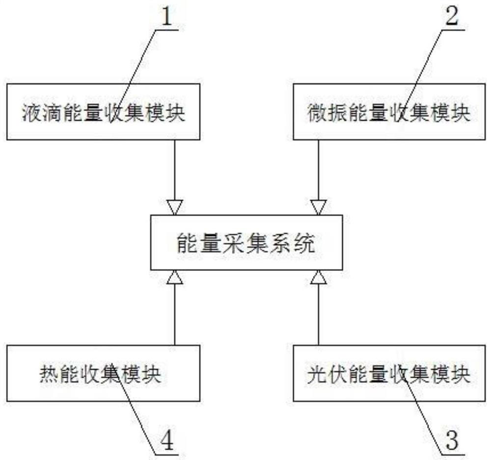
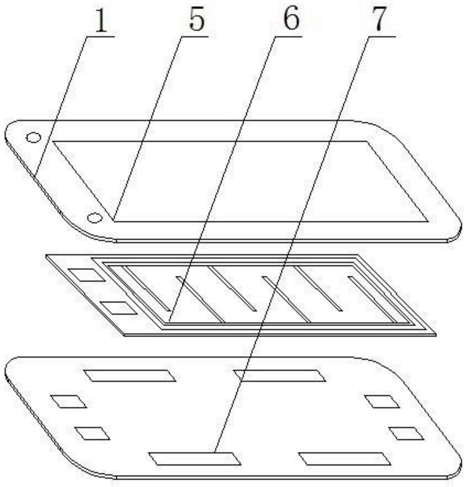
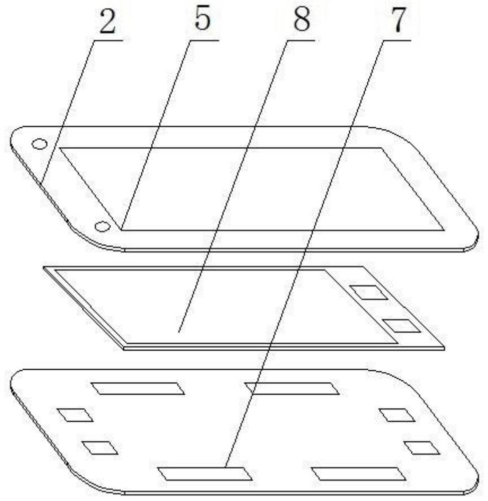
[0038] refer to Figure 1-6 As shown, a highly integrated modular energy harvesting system of the present invention includes an upper protective sticker 5, a droplet energy sticker 6, a microvibration energy sticker 8, a photovoltaic energy sticker 9, a thermal energy collection sticker 10, and a circuit base film 7. The drop energy sticker 6, the micro-vibration energy sticker 8, the photovoltaic energy sticker 9, and the thermal energy collection sticker 10 are respectively used to capture different energies.

[0039] Droplet energy stickers 6, microvibration energy stickers 8, photovoltaic energy stickers 9, and thermal energy collection stickers 10 are all provided with flexible PCBs as skirts, and the four energy stickers are respectively provided with patch electrodes on differe...


PUM


Abstract

The invention discloses a highly-integrated modular energy collection system and application, and belongs to the technical field of energy collection systems. The system comprises an upper protection patch, a liquid drop energy patch, a micro-vibration energy patch, a photovoltaic energy patch, a heat energy collection patch and a circuit substrate film; flexible PCBs are arranged on the peripheries of the four energy patches to serve as skirts, patch-shaped electrodes are arranged on different side edges of the skirts of the four energy patches respectively, and four sets of patch-shaped electrodes are arranged on the upper end face of the circuit substrate film in the circumferential direction; when in use, the required energy patches are stacked layer by layer and then fixed between the upper protective patch and the circuit substrate film, and the patch-shaped electrodes of the adjacent energy patches are arranged in a staggered manner, so that the patch-shaped electrodes of different energy patches are placed in different directions and are respectively butted with the four groups of patch-shaped electrodes on the circuit substrate film; and an external interface electrode is arranged on the upper protection patch and is used for being connected with an external load. According to the invention, different energy can be collected and then applied to different scenes, such as the fields of industry and articles of daily use.

Description

technical field [0001] The invention belongs to the technical field related to energy collection systems, and in particular relates to a highly integrated modular energy collection system and its application. Background technique [0002] Energy harvesting refers to the conversion of weak energy into electrical energy for use by back-end sensors. Usually, the available energy includes weak light energy, weak kinetic energy, thermal energy, etc. Most of the environments where electronic devices are located have a lot of available energy (such as, Electromagnetic fields generated by other devices, vibrations, temperature changes, etc.), convert these energies into electrical energy in a certain way, and usually supply power to small electrical devices (such as cochlea implanted in the human body, etc.), the idea comes from converting mechanical energy or solar energy in nature into Electric energy (hydropower stations, photovoltaic power generation), such as using body heat to...

Claims


Application Information

Patent Timeline
IPC IPC(8): H05K5/00H05K5/02H02J7/35
CPCH05K5/02H05K5/0217H05K5/0247H05K5/00H02J7/35Y02P80/20Y02E10/56
Inventor 聂德志陶凯胡永波范景辉余濛濛曾孝诚张健吕博铭
Owner NORTHWESTERN POLYTECHNICAL UNIV
Learn More