
Textile fabric drying device for textile production and processing

A technology for textile fabrics and drying devices, applied in the textile field, can solve the problems of easy wrinkling of fabrics, long drying time and low efficiency, etc., and achieves the effects of good use stability, convenient leveling and adjustment, and reasonable device structure layout.

Active Publication Date: 2021-10-15
福建辅布司纺织有限公司
View PDF6 Cites 2 Cited by
  • Summary
  • Abstract
  • Description
  • Claims
  • Application Information

AI Technical Summary

Problems solved by technology

[0004] The purpose of the present invention is to solve the problems of long drying time and low efficiency in the prior art and the fabric is easy to wrinkle, and propose a textile fabric drying device for textile production and processing

Method used


Image

  • Textile fabric drying device for textile production and processing
  • Textile fabric drying device for textile production and processing
  • Textile fabric drying device for textile production and processing

Examples


Embodiment 1

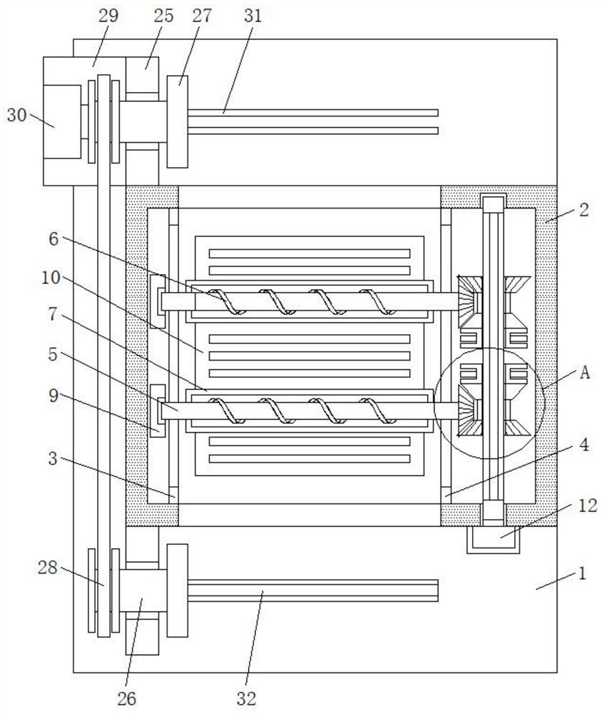
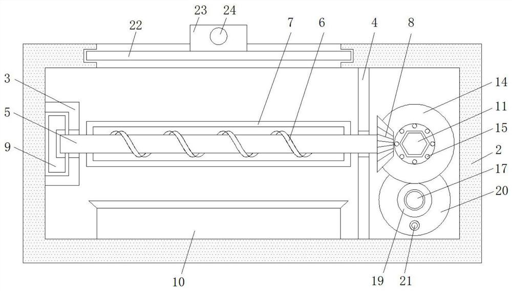
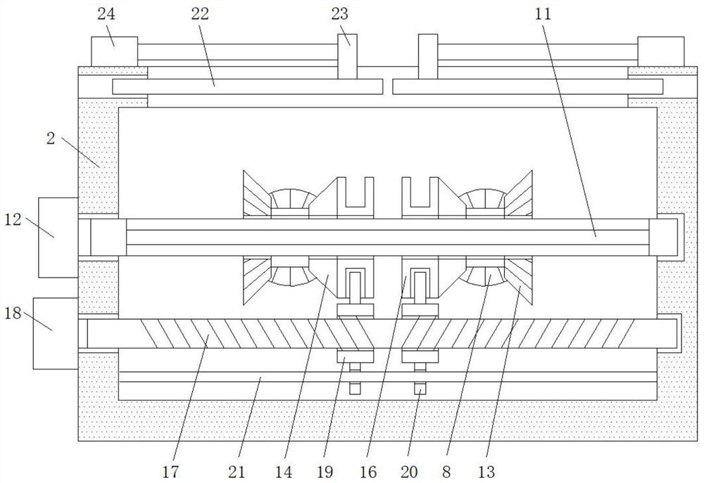
[0031] refer to Figure 1-4 , a textile fabric drying device for textile production and processing, comprising a flat plate 1, a drying box 2 is fixedly arranged on the top side of the flat plate 1, and a limit box 3 and a limiting box 3 are fixedly connected between the vertical side walls of the drying box 2 Support plate 4, and the inner side of limit box 3 slides and is provided with slide block 9, and the side wall body of limit box 3 and the board body of support plate 4 all offer rectangular through holes, and limit box 3 and support plate 4 A rotating shaft 5 is arranged horizontally between them, and the two ends of the rotating shaft 5 pass through two rectangular through holes respectively, and one end is rotationally connected with the slider 9, and the other end is fixedly connected with a bevel gear-8, the rotating shaft 5, the sliding block 9 and Bevel gear-8 is provided with two, two rotating shafts 5 are arranged in parallel, and the shaft body outside of rota...

Embodiment 2

[0037] Such as Figure 1-4 As shown, the present embodiment is basically the same as Embodiment 1, and the more optimized part is that the top side of the flat plate 1 is provided with a fabric conveying and winding assembly, and the fabric conveying and winding assembly includes a riser 25, and the bottom side of the riser 25 is connected to the plate. 1 is fixedly connected, and two vertical plates 25 are arranged symmetrically and are respectively located on both sides of the drying box 2, and a circular shaft 26 is installed in the plate body of the vertical plate 25, and a pulley 28 is installed between one end of the two circular shafts 26 , the other ends are fixedly connected with mounting plates 27, and one side of the two mounting plates 27 is fixedly connected with a winding rod 31 and a mounting rod 32 respectively, and two winding rods 31 are arranged in parallel, one side of the vertical plate 25 Fixedly connected with horizontal plate 29, and motor three 30 are ...

Embodiment 3

[0040] Such as Figure 1-4 As shown, this embodiment is basically the same as Embodiment 1, and the more optimized place is that two door assemblies are arranged symmetrically on the top of the drying box 2, and the door assembly includes a top plate 22, and the top plate 22 is slidably arranged on the drying box 2. In the top wall, and the top side of top plate 22 is fixedly connected with push plate 23, the top wall of drying box 2 is equipped with electric telescopic rod 24, and the output rod of electric telescopic rod 24 is connected with push plate 23 transmissions.

[0041] In this embodiment, the electric telescopic rod 24 is opened, and the output rod of the electric telescopic rod 24 shrinks or extends horizontally, which can drive the push plate 23 to move horizontally, and then drive the top plate 22 to move horizontally in the top wall of the drying box 2. Sliding, so that the top side of the drying box 2 is opened or closed, which is convenient for feeding and so...


PUM


Abstract

The invention discloses a textile fabric drying device for textile production and processing. The textile fabric drying device for textile production and processing comprises a flat plate, wherein a drying box is fixedly arranged on the top side of the flat plate; a limiting box and a supporting plate are fixedly connected between the two vertical side wall bodies of the drying box; sliding blocks is slidably arranged on the inner side of the limiting box; rectangular through holes are formed in one side wall body of the limiting box and a plate body of the supporting plate; rotating shafts are horizontally arranged between the limiting box and the supporting plate; the two ends of each rotating shaft penetrate through the two rectangular through holes correspondingly; one end of each rotating shaft is rotationally connected with the corresponding sliding block; the other end of each rotating shaft is fixedly connected with a first bevel gear; the number of the rotating shafts, the number of the sliding blocks and the number of the first bevel gears are all two; and the two rotating shafts are arranged in parallel. According to the textile fabric drying device for textile production and processing provided by the invention, the fabric drying effect during textile processing is achieved, penetrating and winding feeding, fabric conveying, two-stage drying, flatness adjusting and discharging and winding operation are convenient and fast, the drying efficiency is high, the effect is good, the flatness is guaranteed through fabric stretching, and the practicability is high.

Description

technical field [0001] The invention relates to the technical field of textiles, in particular to a textile fabric drying device for textile production and processing. Background technique [0002] The original meaning of textile is taken from the general term of spinning and weaving. With the continuous development and improvement of the textile knowledge system and discipline system, it also includes textiles produced by non-woven technology, modern three-dimensional weaving technology, and modern electrostatic nano-netting technology. Textile fabrics, that is, knitted fabrics, are divided into weft-knitted fabrics and warp-knitted fabrics according to the weaving method. They are often made of low-elastic polyester yarns or special-shaped polyester yarns, nylon yarns, cotton yarns, and wool yarns. , Change plain stitch, rib plain stitch, double rib plain stitch, jacquard stitch, terry stitch, etc., woven on a warp (weft) knitting machine. [0003] In the drying process o...

Claims


Application Information

Patent Timeline
Patent Type & Authority Applications(China)
IPC IPC(8): B65H20/02B65H23/26B65H23/34F26B13/18F26B23/06F26B25/00F26B25/02
CPCF26B13/183F26B23/06F26B25/003F26B25/02B65H20/02B65H23/34B65H23/26B65H2701/1133B65H2701/174Y02P70/10
Inventor 李文功李荣夏明容
Owner 福建辅布司纺织有限公司
Learn More