
Aorta membrane rupture puncture system with radiography function

An aorta and angiography technology, applied in the field of medical devices, can solve problems such as high requirements, difficult positioning, and difficulty in controlling the window opening direction, and achieve the effect of improving accuracy and simple structure

Pending Publication Date: 2021-10-22
苏州市独墅湖医院苏州大学附属独墅湖医院
View PDF0 Cites 0 Cited by
  • Summary
  • Abstract
  • Description
  • Claims
  • Application Information

AI Technical Summary

Problems solved by technology

However, this method is not only difficult to locate and control the direction of window opening, but also has high requirements for the experience of medical equipment and medical staff.

Method used


Image

  • Aorta membrane rupture puncture system with radiography function
  • Aorta membrane rupture puncture system with radiography function
  • Aorta membrane rupture puncture system with radiography function

Examples


Embodiment 1

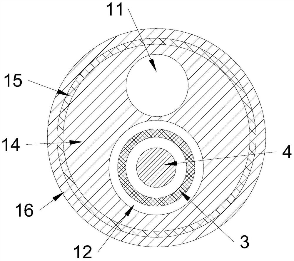
[0022] See attached Figure 1-4 As shown, the aortic membrane puncture system with imaging function of the present invention includes a catheter 1 and an operating handle 2 sheathed on the distal end of the catheter 1 . The catheter 1 is a straight pipe with a first cavity 11 and a second cavity 12 opened along its axial direction. A first guide wire for guiding the catheter 1 into a branch blood vessel is perforated in the first cavity 11 , and the first guide wire exits the first cavity 11 after the catheter 1 is introduced into the branch blood vessel. The puncture needle 3 is installed in the second cavity 12 , and the puncture needle 3 is provided with a guide cavity 31 along its axial direction for the second guide wire 4 to pass through. A side opening 13 communicating with the second cavity 12 is opened on the side wall of the distal end of the catheter 1, and a developing mark is provided at the side opening 13, and the developing mark can be displayed under the devi...

Embodiment 2

[0029] In the present embodiment, only the catheter 1 is different from the embodiment, and other structures are the same. The catheter 1 is a pigtail catheter 1, that is, the catheter 1 between the side opening 13 and the straight hole 17 is a pigtail-shaped contrast section 18, and the contrast section A number of contrast side holes 181 communicating with the first cavity 11 are opened on the side wall of 18 . In Example 1, when the catheter 1 is a straight tube, contrast fluid cannot be injected, but in this embodiment, when the catheter 1 is a pigtail catheter 1 with a contrast section 18, after the first guide wire is withdrawn, the contrast section 18 recovers due to its own elasticity. Shaped into a pigtail, the contrast fluid can be injected into the first cavity 11, and the contrast fluid is discharged through the contrast side hole 181, and is limited in the circle of the contrast portion 18, avoiding direct injection through the straight hole 17, causing blood vesse...


PUM


Abstract

The invention discloses an aorta membrane rupture puncture system with a radiography function. The system comprises a catheter and an operating handle arranged at the far end of the catheter in a sleeving mode, the catheter is provided with a first cavity and a second cavity in the axial direction of the catheter, a first guide wire capable of guiding the catheter into a branch blood vessel is arranged in the first cavity in a penetrating mode, and a puncture needle is assembled in the second cavity; the puncture needle is provided with a guide cavity for the second guide wire to penetrate through in the axial direction of the puncture needle, a side opening communicated with the second cavity is formed in the side wall of the far end of the catheter, a developing mark is arranged at the side opening, the far end of the puncture needle is a needle head portion of an arc-shaped bent structure, and the needle head portion can extend out of the side opening to conduct stent membrane rupture. While precise rupture of the membrane is realized, radiography can be facilitated.

Description

technical field [0001] The invention relates to the technical field of medical devices, in particular to an aortic membrane perforation puncture system with imaging function. Background technique [0002] With the improvement of people's living standards, people's diet is mostly high in oil and salt, which leads to an increasing load on blood vessels, which in turn leads to an increasing incidence of vascular diseases. For such vascular diseases, the existing treatment plan generally uses interventional medical devices to perform interventional surgery. Interventional therapy has become a new treatment alongside surgical treatment and medical treatment. Compared with traditional surgical treatment, interventional treatment has the advantages of less trauma, simplicity, safety, effectiveness, fewer complications and significantly shortened hospital stay. Stent-based vascular repair has gradually been found to have some deficiencies, such as when the covered stent covers bra...

Claims


Application Information

Patent Timeline
Patent Type & Authority Applications(China)
IPC IPC(8): A61F2/06A61F2/07
CPCA61F2/06A61F2/07A61F2002/061
Inventor 黄献琛张喜成
Owner 苏州市独墅湖医院苏州大学附属独墅湖医院
Learn More