Eureka AIR delivers breakthrough ideas for toughest innovation challenges, trusted by R&D personnel around the world.

A wet purification equipment for petroleum refining

A technology of wet purification and petroleum refining, which is applied in the direction of chemical instruments and methods, the use of liquid separation agents, separation methods, etc., can solve the problems of affecting the safety of workers, inconvenient operation, and large consumption of purification liquid, etc., and achieve efficient purification of pollution The effect of gas, increasing the spraying range, and purifying a wide area

Active Publication Date: 2022-05-13
东营思达石油化工有限公司
View PDF0 Cites 0 Cited by
  • Summary
  • Abstract
  • Description
  • Claims
  • Application Information

AI Technical Summary

Problems solved by technology

A large amount of waste gas will be emitted during the petroleum refining process. The pollutant components are complex, highly toxic, diverse, concentrated and harmful. The regeneration flue gas discharged from the catalytic cracking unit of the refinery contains dust, carbon monoxide, nitrogen oxides and sulfur dioxide. Although the waste gas is discharged after treatment, it cannot be 100% cleaned. As a result, the dust content and a small amount of harmful gas in the gas near the oil refinery are higher than those in other places. The dust and a small amount of harmful gas flow into the factory area and affect the work. personnel safety
In addition, the current air purification equipment in petroleum refineries purifies the polluted gas for a period of time, and the built-in filter screen needs to be replaced frequently, the consumption of purification liquid is large, the cost is high, and the operation is inconvenient. Therefore, the present invention proposes a petroleum refinery The wet purification equipment used in the production is used to solve the above problems

Method used


Image

  • A wet purification equipment for petroleum refining
  • A wet purification equipment for petroleum refining
  • A wet purification equipment for petroleum refining

Examples


Embodiment Construction

[0028] The following will clearly and completely describe the technical solutions in the embodiments of the present invention with reference to the drawings in the embodiments of the present invention.

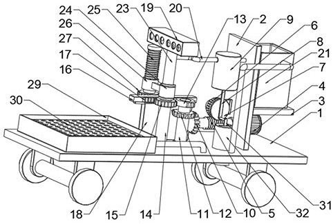
[0029] see figure 1 , in an embodiment of the present invention, a wet purification equipment for petroleum refining, the wet purification equipment for petroleum refining includes a bottom plate 1 and a fixed plate 2 fixedly installed on the bottom plate 1, the fixed plate 2 is fixed A horizontal plate 3 parallel to the bottom plate 1 is installed, and the wet purification equipment for petroleum refining also includes:

[0030] Nozzle 19, said nozzle 19 is movably arranged on said bottom plate 1, and is used for outputting purification liquid to places requiring air purification;

[0031] A reciprocating mechanism, the reciprocating mechanism is movably arranged on the bottom plate 1 and connected with the nozzle 19, and the reciprocating mechanism drives the nozzle 19 to r...


PUM


Abstract

The invention relates to the technical field of petrochemical production equipment, and discloses a wet purification equipment for petroleum refining. Its technical scheme is as follows: the wet purification equipment for petroleum refining includes a bottom plate and a fixed plate fixedly installed on the bottom plate, a horizontal plate parallel to the bottom plate is fixedly installed on the fixed plate, and the oil refining The wet purification equipment also includes: a nozzle, the nozzle is movably arranged on the bottom plate; a reciprocating mechanism, the reciprocating mechanism is movably arranged on the bottom and connected with the nozzle; a lifting assembly, the lifting assembly is connected to the The reciprocating mechanism is connected and movably installed on the base plate; the driving mechanism is connected with the reciprocating mechanism. The invention efficiently purifies the polluted gas produced in the petroleum refining process, and the purification liquid and dust in the purification process can be automatically screened, and the purification liquid can be recycled, which greatly reduces the cost and is safe and environment-friendly.

Description

technical field [0001] The invention relates to the technical field of petrochemical production equipment, in particular to a wet purification equipment for petroleum refining. Background technique [0002] The main production units in petroleum refineries usually include: crude oil distillation (atmospheric and vacuum distillation), thermal cracking, catalytic cracking, hydrocracking, petroleum coking, catalytic reforming, refinery gas processing, petroleum product refining, etc. The main production Gasoline, jet fuel, kerosene, diesel, fuel oil, lubricating oil, petroleum wax, petroleum pitch, petroleum coke and various petrochemical raw materials. A large amount of waste gas will be emitted during the petroleum refining process. The pollutant components are complex, highly toxic, diverse, concentrated and harmful. The regeneration flue gas discharged from the catalytic cracking unit of the refinery contains dust, carbon monoxide, nitrogen oxides and sulfur dioxide. Altho...

Claims


Application Information

Patent Timeline
Patent Type & Authority Patents(China)
IPC IPC(8): B01D47/08B01D36/00
CPCB01D47/08B01D36/001B01D2247/04
Inventor 黄东晓
Owner 东营思达石油化工有限公司
Why Eureka
Eureka Blog
Learn More