Device and method for monitoring depth changes of groove of polishing pad
A groove depth and polishing pad technology, applied in the field of polishing pads, can solve the problem of inconvenient monitoring of changes in the groove depth of polishing pads, and achieve the effects of reducing product cost, personnel workload, and convenient monitoring.
- Summary
- Abstract
- Description
- Claims
- Application Information
AI Technical Summary
Problems solved by technology
Method used
Image
Examples
Embodiment 1
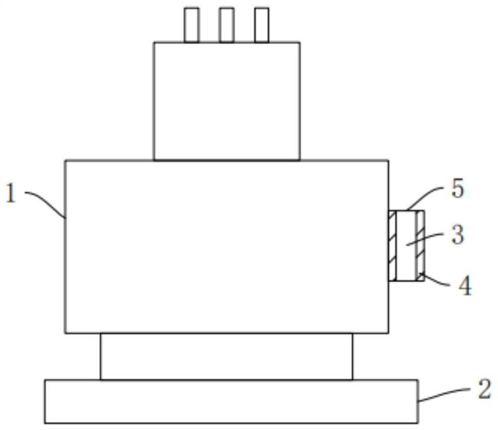
[0034] refer to figure 1 The present invention provides a device for monitoring the variation of the groove depth of a polishing pad, including a dresser 1, a dresser 2, a sensor 3, a monitoring system and an alarm system, the dresser 1 is used to connect to an external body; the dresser 2 is connected to the The dresser 1 is slidingly connected for dressing the polishing pad; the sensor 3 is connected with the dresser 1 for measuring the target distance between the sensor 3 and the dressing disc 2; the monitoring system is connected with the sensor 3 Electrically connected, used to receive the target distance, and compare the target distance with a preset threshold; the alarm system is electrically connected to the monitoring system, and used to send when the target distance is greater than the preset threshold Alarm information.
[0035] Through the above settings, when the operator needs to monitor the groove depth of the polishing pad, the dresser 1 is connected to the ex...
Embodiment 2
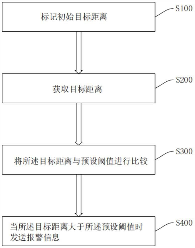
[0041] refer to Figure 2-3 , a kind of method for monitoring the variation of polishing pad groove depth provided by the present invention, comprises the following steps:
[0042] Step S100 , marking an initial target distance, wherein the initial target distance is the shortest linear distance from the sensor 3 to the conditioning disc 2 before the conditioning disc 2 abuts against the polishing pad and the polishing pad is dressed.
[0043] Through the above settings, there is a small gap in the thickness of different polishing pads, and a more accurate preset threshold can be obtained by marking the initial position, so that the change of the groove depth of the polishing pad is more accurately measured.
[0044] Step S200, acquiring a target distance, wherein the target distance is the shortest straight-line distance from the sensor 3 to the trimming disc 2;
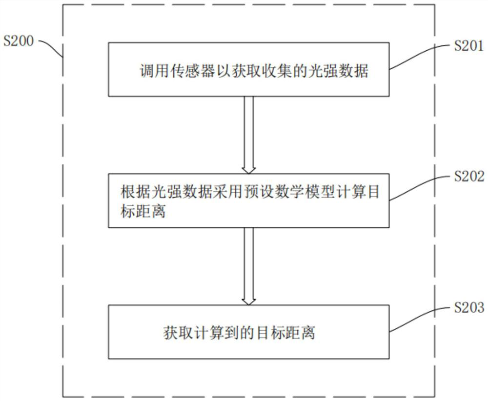
[0045] Specifically, obtaining the target distance includes:
[0046] S201, calling the sensor 3 to obtain the ...
Embodiment 3
[0058] refer to Figure 4 , the embodiment of the present invention also provides a computer device, as shown in the figure, the device includes a processor 6 and a memory 7, wherein the processor 6 and the memory 7 can be connected through a bus 8 or other ways, in the figure, through a bus 8 connection as an example.
[0059] The processor 6 may be a central processing unit 6 (Central Processing Unit, CPU). Processor 6 can also be other general purpose processor 6, digital signal processor 6 (Digital Signal Processor, DSP), graphic processor 6 (Graphics Processing Unit, GPU), embedded neural network processor 6 (Neural-network Processing Unit, NPU) or other dedicated deep learning coprocessor 6, application specific integrated circuit (Application Specific Integrated Circuit, ASIC), field programmable gate array (Field-Programmable GateArray, FPGA) or other programmable logic devices, discrete gate or transistor logic devices , discrete hardware components and other chips,...
PUM
 Abstract
Description
Claims
Application Information
 - R&D
- Intellectual Property
- Life Sciences
- Materials
- Tech Scout
- Unparalleled Data Quality
- Higher Quality Content
- 60% Fewer Hallucinations
Browse by: Latest US Patents, China's latest patents, Technical Efficacy Thesaurus, Application Domain, Technology Topic, Popular Technical Reports.
© 2025 PatSnap. All rights reserved.Legal|Privacy policy|Modern Slavery Act Transparency Statement|Sitemap|About US| Contact US: help@patsnap.com


