Non-contact glass capillary diameter control method

A glass capillary, non-contact technology, applied in the field of light, can solve problems such as coupler signal loss, reduce signal loss, avoid breakage and collapse, and ensure airtightness

Inactive Publication Date: 2021-10-22
武汉介研新材料有限公司
View PDF0 Cites 4 Cited by
  • Summary
  • Abstract
  • Description
  • Claims
  • Application Information

AI Technical Summary

Problems solved by technology

[0002] With the development of optical fiber technology and the development of optical fiber communication and sensor industries, optical fiber devices have become one of the most important optoelectronic devices. Optical fiber couplers are components used to realize optical signal splitting or combining, and to extend optical fiber links. , belongs to the field of optical passive components, and can be applied in telecommunication networks, cable TV networks, user loop systems, and regional networks. The current fiber optic couplers use quartz capillary tubes as sleeves to connect multiple single-core optical fibers. Tapering reduces the overall diameter of the capillary and single-core fiber, and achieves coupling with multi-core fiber fusion. However, the uniformity of the diameter of the glass capillary in the current coupler and the single control of the diameter during the taper process often make the prepared coupler The signal loss is serious, so we propose a non-contact glass capillary diameter control method to solve the above problems

Method used


Image

  • Non-contact glass capillary diameter control method
  • Non-contact glass capillary diameter control method
  • Non-contact glass capillary diameter control method

Examples


Embodiment Construction

[0031] The technical solutions in the embodiments of the present invention will be clearly and completely described below with reference to the accompanying drawings in the embodiments of the present invention. Obviously, the described embodiments are only a part of the embodiments of the present invention, but not all of the embodiments. Based on the embodiments of the present invention, all other embodiments obtained by those of ordinary skill in the art without creative efforts shall fall within the protection scope of the present invention.

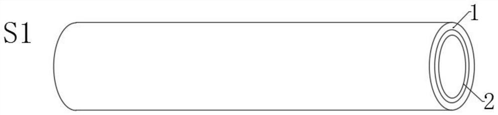
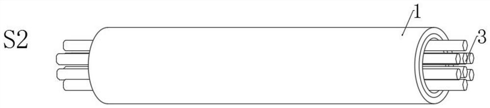
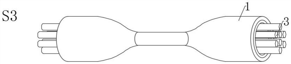
[0032] see Figure 1-5 , the present invention provides a technical solution: a non-contact glass capillary diameter control method, comprising the following steps:

[0033] S1. Use vapor deposition equipment to deposit a fluorine-doped quartz low-refractive index layer 2 in the quartz base 1 tube, use hydrofluoric acid to etch, remove and polish the outer wall of the base tube 1, and then use a high-precision drawing tower to draw a ...


PUM

PropertyMeasurementUnit
diameteraaaaaaaaaa
diameteraaaaaaaaaa

Abstract

The invention discloses a non-contact glass capillary diameter control method which comprises the following steps: depositing a fluorine-doped quartz low-refractive-index layer in a quartz base tube by using vapor deposition equipment, corroding and polishing the outer wall of the base tube by using hydrofluoric acid, and then drawing to manufacture a low-refractive-index quartz capillary; selecting a corresponding number of single-core optical fibers, removing coating layers of the single-core optical fibers through chemical corrosion, and inserting the plurality of single-core optical fibers into a low-refractive-index quartz capillary; using a tapering system for carrying out equal-proportion heat insulation tapering on the quartz capillary sleeve and the single-core optical fiber, thinning the quartz capillary, reducing the diameter at the taper waist to be equal to that of the multi-core optical fiber, and degrading the diameter of the internal single-core optical fiber to be matched with the fiber core of the multi-core optical fiber; measuring the tapering area, observing the diameter change of the tapering area, and cutting the tapering waist by using an optical fiber cutter to obtain a tapering body; and aligning and welding the cut cone and the multi-core optical fiber, and finally packaging to form the single-core optical fiber and multi-core optical fiber coupler.

Description

technical field [0001] The invention relates to the technical field of light, in particular to a non-contact glass capillary diameter control method. Background technique [0002] With the development of optical fiber technology and the development of optical fiber communication and sensor industry, optical fiber devices have become one of the most important optoelectronic devices. Optical fiber couplers are used to achieve optical signal splitting or combining, and are used to extend optical fiber links. , belongs to the field of optical passive components, and will be applied in telecommunication networks, cable TV networks, user loop systems, and local area networks. The current fiber couplers are all single-core optical fibers are sleeved through quartz capillaries as sleeves. Tapering reduces the overall diameter of the capillary and the single-core fiber, and splices with multi-core fiber to achieve coupling. However, the uniformity of the diameter of the glass capilla...

Claims


Application Information

Patent Timeline
Patent Type & Authority Applications(China)
IPC IPC(8): G02B6/255G02B6/25G02B6/26C03B37/014C03B37/027
CPCG02B6/2552G02B6/2553G02B6/25G02B6/26C03B37/014C03B37/027
Inventor 朱久荣张彧辰
Owner 武汉介研新材料有限公司
Why Eureka
Try Eureka