Down-hole impact high-pressure jet grouting composite pile forming method

A high-pressure rotary grouting pile and high-pressure rotary grouting technology are applied in the direction of sheet pile walls, soil protection, construction, etc., which can solve problems such as delay in construction period, short construction period, and high rate of pile breakage of inclined piles, so as to ensure the depth of rock-socketed, Improve the strength of the soil between the piles and the effect of increasing the bearing capacity of the single pile

Inactive Publication Date: 2021-10-26
建材桂林地质工程勘察院有限公司
View PDF10 Cites 0 Cited by
  • Summary
  • Abstract
  • Description
  • Claims
  • Application Information

AI Technical Summary

Problems solved by technology

[0002] In the field of geotechnical engineering, perforated cast-in-situ piles are suitable for geological conditions where there are multi-layered caves underground, but the caves are small and the upper roof is thin. , pouring concrete causes concrete loss and is difficult to control
Bored piles can be embedded in rocks, have a high bearing capacity, and can drill through underground boulders and interlayers. However, buried drills, dropped drills, and skewed piles are prone to occur in bedrock with many cracks. Solving these problems seriously delays the construction period and is economical. Low benefit; prestressed pipe piles have the advantages of high pile bearing capacity and short construction period. They are suitable for geological conditions such as silt, soil caves, quicksand, and connected underground rivers. The rate is high, and sometimes super-long piles appear
To sum up, it is difficult for a single pile type to meet the requirements of technical feasibility, reliable quality, and economical rationality at the same time.

Method used


Image

  • Down-hole impact high-pressure jet grouting composite pile forming method
  • Down-hole impact high-pressure jet grouting composite pile forming method
  • Down-hole impact high-pressure jet grouting composite pile forming method

Examples


Embodiment 1

[0028] Select high-quality R42.5# ordinary silicon cement, and calibrate the maximum water level line according to the size of the mixing tank, water-cement ratio, and mud specific gravity. Add cement according to the water-cement ratio of 1:1, and stir thoroughly to determine whether the specific gravity of the mud reaches the trial proportion of 1.47. If it cannot reach the proportion, continue to add cement until it reaches the trial proportion of cement slurry. The mixing time cannot exceed the initial setting time of the cement slurry, and it is filtered through two filters to prevent the nozzle from being blocked.

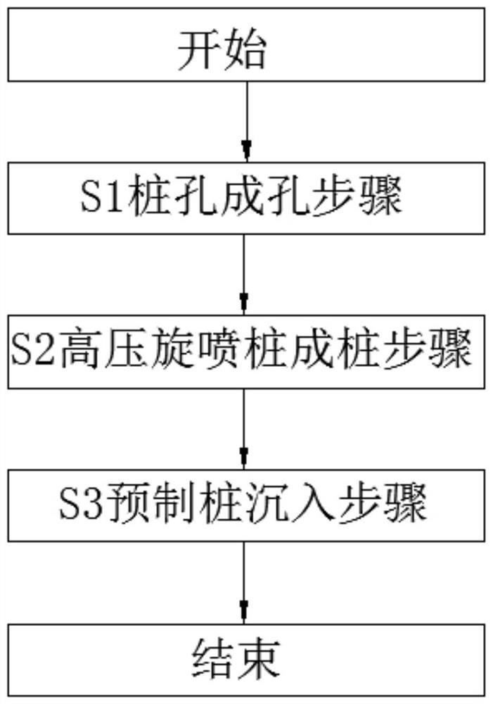
[0029] S1 pile hole forming steps: After the down-the-hole impact high-pressure rotary grouting drilling rig is in place, the deviation of verticality after correction does not exceed ±0.5%, and the down-the-hole hammer is driven by the 20Mpa high-pressure air driven by the impactor at the bottom of the drill pipe. , until the depth reaches the design depth o...

Embodiment 2

[0038] Select high-quality R42.5# ordinary silicon cement, and calibrate the maximum water level line according to the size of the mixing tank, water-cement ratio, and mud specific gravity. Add cement according to the water-cement ratio of 1:1, and stir fully to determine whether the specific gravity of the mud reaches the trial proportion of 1.47. If it cannot reach the proportion, continue to add cement until it reaches the trial proportion of cement slurry. The mixing time cannot exceed the initial setting time of the cement slurry, and it is filtered through two filters to prevent the nozzle from being blocked.

[0039] S1 pile hole forming steps: After the down-the-hole impact high-pressure rotary grouting drilling rig is in place, the deviation of verticality after correction does not exceed ±0.5%, and the down-the-hole hammer is driven by the 20Mpa high-pressure air driven by the impactor at the bottom of the drill pipe. , until the depth reaches the design depth of 10m...

Embodiment 3

[0047] Select high-quality R42.5# ordinary silicon cement, and calibrate the maximum water level line according to the size of the mixing tank, water-cement ratio, and mud specific gravity. Add cement according to the water-cement ratio of 1:1, and stir thoroughly to determine whether the specific gravity of the mud reaches the trial proportion of 1.47. If it cannot reach the proportion, continue to add cement until it reaches the trial proportion of cement slurry. The mixing time cannot exceed the initial setting time of the cement slurry, and it is filtered through two filters to prevent the nozzle from being blocked.

[0048] S1 pile hole forming steps: After the down-the-hole impact high-pressure rotary grouting drilling rig is in place, the deviation of verticality after correction does not exceed ±0.5%, and the down-the-hole hammer is driven by the 25Mpa high-pressure air driven by the impactor at the bottom of the drill pipe. , until the depth reaches the design depth o...


PUM


Abstract

The invention provides a down-hole impact high-pressure jet grouting composite pile forming method. The method comprises the steps of S1, pile hole forming, S2, high-pressure jet grouting pile forming and S3, precast pile sinking and specifically comprises the steps that a down-hole hammer is driven by high-pressure air to impact and drill a formed pile hole, meanwhile, an ejector nozzle of a down-the-hole impact high-pressure jet-grouting drilling machine ejects high-pressure jet-grouting cement slurry to cut, stir and reinforce soil around the pile to form a uniform cement-soil mixture, and then a pile hammering machine or a pile static pressing machine is adopted to drive a precast pile with the diameter smaller than the diameter of the formed hole of the down -hole hammer into the bottom of the hole along the center of the high-pressure jet-grouting pile, therefore a composite pile is formed; the pile forming method can be applied to the aspects of foundation treatment, pile foundations, foundation pit supporting, waterproof curtains, elimination or reduction of foundation liquefaction, expansion and shrinkage of expansive soil and the like, has the advantages that the quality is stable and reliable, construction is convenient, the construction period is shortened, materials and construction cost are saved, and the manufacturing cost is reduced.

Description

technical field [0001] The invention belongs to the field of geotechnical engineering, and in particular relates to a pile-forming method of a submerged-hole impact high-pressure rotary grouting composite pile. Background technique [0002] In the field of geotechnical engineering, perforated cast-in-situ piles are suitable for geological conditions where there are multi-layered caves underground, but the caves are small and the upper roof is thin. , pouring concrete causes concrete loss and is difficult to control. Bored piles can be embedded in rocks, have a high bearing capacity, and can drill through underground boulders and interlayers. However, buried drills, dropped drills, and skewed piles are prone to occur in bedrock with many cracks. Solving these problems seriously delays the construction period and is economical. Low benefit; prestressed pipe piles have the advantages of high pile bearing capacity and short construction period. They are suitable for geological ...

Claims


Application Information

Patent Timeline
Patent Type & Authority Applications(China)
IPC IPC(8): E02D5/46E02D5/30E02D7/00E02D15/04E02D3/00E02D3/12
CPCE02D5/46E02D5/30E02D7/00E02D15/04E02D3/00E02D3/12
Inventor 蒋仕清姜大伟汤湘军乌青松柳东黄俊辉
Owner 建材桂林地质工程勘察院有限公司
Why Eureka
Try Eureka