Production and assembling equipment for TST-PVC floor

A technology of TST-PVC and assembling equipment, which is applied to the device, coating, and pretreatment surface of the surface coating liquid, which can solve the problems of difficult adjustment and transformation, single equipment performance, low floor efficiency, etc., to save adjustment. Time, simple and compact structure, high work efficiency

Active Publication Date: 2021-10-29
洁玛新材料股份有限公司
View PDF6 Cites 0 Cited by
  • Summary
  • Abstract
  • Description
  • Claims
  • Application Information

AI Technical Summary

Problems solved by technology

[0003] The existing plastic floor production equipment has a complex structure, a long production line, low floor production efficiency, and single equipment performance. When processing different types of products, it is difficult to adjust and transform, and the cost is high.

Method used


Image

  • Production and assembling equipment for TST-PVC floor
  • Production and assembling equipment for TST-PVC floor
  • Production and assembling equipment for TST-PVC floor

Examples


Embodiment 1

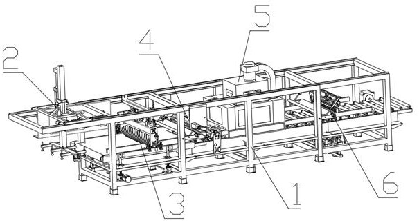
[0032] Embodiment 1: as figure 1 As shown, a production and assembly equipment for TST-PVC flooring includes a conveyor frame 1, a feeding device 2, a printing device 3, a coating device 4, a drying device 5 and a cutting device 6, and the conveyor frame 1 includes a main frame , conveying roller, baffle plate and driving motor, the feeding device 2 sends the product to the printing device 3 for printing, and then the printing device 3 sends the product to the conveying roller, and the conveying roller conveys the product to the coating device 4, The drying device 5 and the cutting device 6 respectively carry out the coating of UV paint, the drying of UV paint and the cutting of the floor, and then the conveying roller continues to convey and discharge the cut product, and the conveying roller is driven by the driving motor to rotate .

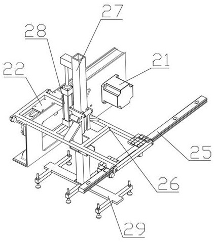
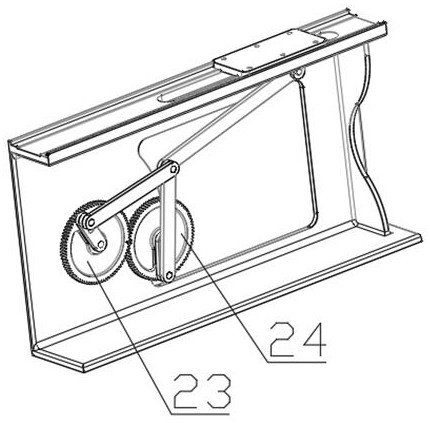
[0033] Firstly, the material is loaded by the feeding device 2, such as figure 2 with image 3 As shown, the feeding device 2 includes a ...

Embodiment 2

[0038] Embodiment 2: The difference between this embodiment and Embodiment 1 is that in order to realize the production and assembly of floors of different thicknesses, such as Figure 4 As shown, the printing device 3 is also provided with four worm-gear elevators 39 below the belt conveyor 37. The four worm-gear elevators 39 are driven by servo motors and can precisely adjust the height of the lift, thereby controlling the height of the belt conveyor 37. And cooperate with the adjustment cylinder 36 to drive the printing roller 381 to move up and down, which can satisfy the printing on the bottom plate of various thicknesses; correspondingly, as Image 6 with Figure 7 As shown, the compression cylinder 413 of the first compression assembly 41 drives the compression roller 412 to move up and down, and then adjusts the height of the compression roller 412 to adapt to compacting floors of different thicknesses. The thickness adjustment cylinder of the coating device 4 42 can ...

Embodiment 3

[0039] Embodiment 3: The difference between this embodiment and embodiment 1 is that in order to realize the UV coating of different widths to the bottom plate, as Image 6 with Figure 7 As shown, the coating device 4 is also provided with an adjustment rack 47, a gear box 48 and a rubber baffle 49, and the paint tank 43 is divided into a plurality of paint chambers. Drive the gears in the gear box 48 to rotate through the servo motor, thereby driving the gear box 48 to slide on the adjustment rack 47, and then driving the rubber baffles 49 to move back and forth, adjusting the distance between the two rubber baffles 49 to meet the needs The width of the coating enables the UV paint to be coated on the floor between the two rubber baffles 49; by adjusting the rubber baffles 49, coatings of different widths are realized, which further improves the compatibility of the equipment and reduces the equipment cost. the cost of.


PUM


Abstract

The invention discloses production and assembling equipment for a TST-PVC floor. The production and assembling equipment comprises a conveying rack, a feeding device, a printing device, a coating device, a drying device and a cutting device, wherein the feeding device is arranged at the left end of the conveying rack, and the printing device, the coating device, the drying device and the cutting device are sequentially arranged in a frame of the conveying rack from left to right; the printing device comprises a cantilever beam, deviation rectifying fixing plates are arranged at the front end and the rear end of the cantilever beam, deviation rectifying air cylinders are arranged on the two deviation rectifying fixing plates, deviation rectifying adjusting plates are arranged at the output ends of the two deviation rectifying air cylinders, deviation rectifying shafts are arranged at the left ends of the two deviation rectifying adjusting plates, the upper ends of the two deviation rectifying shafts are fixed on a tensioning beam, the tensioning beam is fixed at the top end of the conveying rack, an adjusting air cylinder is arranged in the middle of the cantilever beam in a sliding mode, and the output end of the adjusting air cylinder is fixed on the tensioning beam. The production and assembling equipment is compact in structure and high in working efficiency and has good market application value.

Description

technical field [0001] The invention belongs to the field of floor production, and in particular relates to a production and assembly equipment for TST-PVC floor. Background technique [0002] TST-PVC floor is also compared with plastic floor. The main material is polyvinyl chloride. Plastic floor is a new type of light-weight floor decoration material that is very popular in the world today, also known as "light-weight floor material". It is environmentally friendly, ultra-light Ultra-thin, strong wear resistance, anti-skid, waterproof and other advantages are gradually being used in various places such as families, hospitals, schools, office buildings, factories, public places, supermarkets, businesses, and stadiums. [0003] The existing plastic floor production equipment has a complex structure, a long production line, low floor production efficiency, and single equipment performance. When processing different types of products, it is difficult to adjust and transform, a...

Claims


Application Information

Patent Timeline
IPC IPC(8): B26D7/02B26D1/06B26D7/26B29C59/04B29C37/00B05C11/04B05C13/02B05D3/06
CPCB26D7/025B26D1/06B26D7/2628B29C59/043B29C59/002B05C13/02B05C11/04B05D3/067Y02P70/10
Inventor 庄宝豪刘楚涛王鸿琛
Owner 洁玛新材料股份有限公司
Why Eureka
Try Eureka