Electromagnetic water meter circuit with high efficiency and small interference

A high-efficiency, excitation circuit technology, applied in the fields of electromagnetic water meter and electromagnetic flowmeter flow measurement, power supply circuit design, and excitation circuit design, can solve the problems of large power consumption of the whole machine, large signal influence, low excitation efficiency, etc., and achieve excitation High efficiency, low excitation voltage, and reduced self-consumption

Pending Publication Date: 2021-10-29
上海肯特仪表股份有限公司
View PDF0 Cites 0 Cited by
  • Summary
  • Abstract
  • Description
  • Claims
  • Application Information

AI Technical Summary

Problems solved by technology

[0002] Electromagnetic water meter has many advantages for fluid flow rate measurement. Compared with other ultrasonic water meters and mechanical water meters, it has the advantages of high measurement accuracy, good linearity, wide range ratio, wear resistance, and no temperature influence, so it is widely used. It is used in urban water supply industry and agricultural irrigation industry; the principle of electromagnetic measurement of fluid flow is: according to Faraday's law of electromagnetic induction, when a conductive fluid flows through a uniformly distributed magnetic field, due to the action of cutting magnetic force lines, the contact with the fluid can be detected on the electrodes of the conductor. The average speed is proportional to the induced electromotive force. Therefore, the volume flow rate is calculated according to the cross-sectional area of ​​the pipeline by detecting the induced electromotive force. At present, the existing electromagnetic water meter circuit has low excitation efficiency, large power consumption of the whole machine, many types of power supply voltage, and extreme In order to solve the above problems, our company has developed an electromagnetic water meter detection circuit with high efficiency and low interference. The patent of this invention can improve the excitation efficiency, reduce the excitation power consumption and the power consumption of the whole machine, Simplify the type of power supply, filter out polarization voltage interference, further reduce battery consumption, and improve flow measurement accuracy

Method used


Image

  • Electromagnetic water meter circuit with high efficiency and small interference
  • Electromagnetic water meter circuit with high efficiency and small interference
  • Electromagnetic water meter circuit with high efficiency and small interference

Examples


Embodiment Construction

[0043] The technical solutions of the present invention will be further described in detail below in conjunction with specific embodiments, and the scope of protection of the present invention will not be limited to the following statements.

[0044] In this patent, some parameters are introduced in order to explain the problem, such as voltage value, current value, etc. These introductions are only for the convenience of explaining the problem. The parameters such as caliber and turndown ratio have been adjusted, but as long as the circuit or similar structure of this patent is used, it should also be protected by this patent.

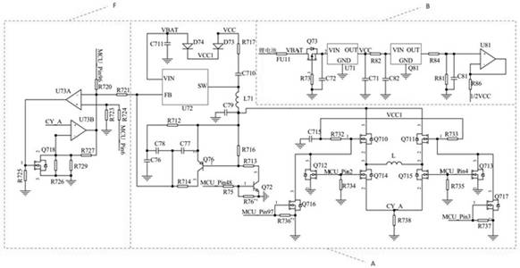
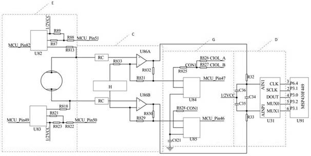
[0045] Such as figure 1 , figure 2 , an electromagnetic water meter circuit with high efficiency and low interference is composed of high-efficiency excitation circuit A of flow control voltage source, power supply circuit B without negative power supply, amplification and processing circuit C of isolated polarization voltage, AD conversion circuit ...


PUM


Abstract

The invention relates to an electromagnetic water meter circuit with high efficiency and small interference, in particular to an excitation circuit design and a power supply circuit design. Theelectromagnetic water meter circuit comprises a flow control voltage source efficient excitation circuit, a power supply circuit without a negative power supply, an amplification and processing circuit of isolation polarization voltage, an A / D conversion circuit, an empty pipe detection circuit, an excitation voltage detection circuit and a coil current detection circuit. According to the invention, excitation efficiency can be improved, excitation power consumption and overall power consumption can be reduced, power supply types can be simplified, polarization voltage interference can be filtered, battery consumption can be further reduced, and the flow measurement precision can be improved.

Description

technical field [0001] The invention relates to the field of flow measurement of electromagnetic water meters and electromagnetic flowmeters, in particular to the design of excitation circuits and power supply circuits. The invention can improve excitation efficiency, reduce power consumption of electromagnetic water meters, and filter out polarization voltage interference, and is suitable for battery-powered electromagnetic The water meter adopts the present invention, which can prolong the service life of the electromagnetic water meter and improve the accuracy of flow measurement. Background technique [0002] Electromagnetic water meter has many advantages for fluid flow rate measurement. Compared with other ultrasonic water meters and mechanical water meters, it has the advantages of high measurement accuracy, good linearity, wide range ratio, wear resistance, and no temperature influence, so it is widely used. It is used in urban water supply industry and agricultural ...

Claims


Application Information

Patent Timeline
Patent Type & Authority Applications(China)
IPC IPC(8): G01F1/60G05F1/56
CPCG01F1/60G05F1/56
Inventor 费战波张俊锋高超李恒阳
Owner 上海肯特仪表股份有限公司
Why Eureka
Try Eureka