Bone repairstentfor directionally inducing bone tissue differentiation

A technology of directional induction and bone repair, applied in the field of biomedical engineering, can solve problems such as ignoring the influence of bone cells, and achieve the effects of directional bone tissue differentiation, enhancement of osteogenic performance, and promotion of directional induction and differentiation

Active Publication Date: 2021-11-02
QILU UNIV OF TECH
View PDF7 Cites 0 Cited by
  • Summary
  • Abstract
  • Description
  • Claims
  • Application Information

AI Technical Summary

Problems solved by technology

[0004] The bone repair scaffolds in the prior art can meet the requirements of osteogenesis at the macroscopic level, but ignore the key factor that determines the osteogenic performance---the influence of bone cells

Method used


Image

  • Bone repairstentfor directionally inducing bone tissue differentiation
  • Bone repairstentfor directionally inducing bone tissue differentiation
  • Bone repairstentfor directionally inducing bone tissue differentiation

Examples


Embodiment

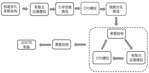
[0043] A bone repair scaffold for directional induction of bone tissue differentiation, specifically comprising the following steps:

[0044] 1. Structural Design of Bone Repair Scaffold

[0045] The bone repair scaffold is designed on the basis of the unit cell structure. The characteristics of the unit cell determine the characteristics of the overall scaffold. It can be arranged in various shapes, which is convenient and quick to meet the precise repair of bone defects.

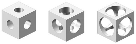
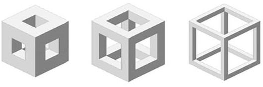
[0046] The scaffold unit cell is based on a cube with a side length of 500 microns, and its structure is designed. The unit cell size of 500 microns enables high-precision repair of bone defects.

[0047] In order to meet the mechanical properties and pore size requirements, three different unit cell structures were preliminarily designed, and each structure corresponds to three different pore sizes.

[0048] Structure 1 is a cylindrical unit cell structure, and the diameters of the circular holes are 200 ...


PUM

PropertyMeasurementUnit
sizeaaaaaaaaaa

Abstract

The invention belongs to the technical field of biomedical engineering, and particularly relates to a bone repair stent for directionally inducing bone tissue differentiation. The functions of the stent are realized through structural design. The method comprises the following steps: constructing a porous unit cell structure; performing analogue simulation of a compression experiment on the porous unit cell structure through a finite element analysis method to obtain a structure matched with the mechanical properties of the human bone; carrying out cell loading on the obtained porous unit cell structure, and judging the osteogenic ability of cell differentiation and bone tissue differentiation through a computational fluid dynamics method; feeding back a calculation fluid dynamics result to finite element analysis, and carrying out structural modification to obtain a bone repair scaffold porous unit cell model which better conforms to directional induction bone tissue differentiation; and preparing the high-precision bone repair stent by using a 3D printing technology. The bone repair stent provided by the invention has better osteogenesis performance and can be used for accurately repairing bone defect parts.

Description

technical field [0001] The invention belongs to the technical field of biomedical engineering, and in particular relates to a bone repair scaffold for directional induction of bone tissue differentiation. Background technique [0002] The growing demand for bone grafts and the limitations of autografts and allografts have prompted new developments in bone tissue engineering. The use of tissue engineering methods and means to repair tissue defects is a new treatment model with broad application prospects and is a hot spot in current medical research. At the same time, the rise of 3D printing technology has broken the limitations of traditional manufacturing processes and has become an ideal process for preparing bone repair scaffolds. [0003] At present, most bone repair scaffolds are mainly researched and designed for material and mechanical properties, and obtain better osteogenic performance from a macro perspective. Bone repair scaffolds usually have the following attr...

Claims


Application Information

Patent Timeline
Patent Type & Authority Applications(China)
IPC IPC(8): A61L27/12A61L27/56A61L27/50A61L27/54B33Y80/00B33Y70/00B33Y10/00
CPCA61L27/12A61L27/56A61L27/50A61L27/54B33Y80/00B33Y70/00B33Y10/00A61L2430/02A61L2300/112A61L2300/412
Inventor 史岩彬付孟广吴玉尧王飞王丽冯益华唐炳涛林贵梅
Owner QILU UNIV OF TECH
Why Eureka
Try Eureka