Eureka AIR delivers breakthrough ideas for toughest innovation challenges, trusted by R&D personnel around the world.

Wall surface rolling-type blade with active jet structure

A rolling and active technology, which is applied to the supporting elements of the blade, engine elements, machines/engines, etc., can solve the problem of poor optimization of airfoil lift-drag and flow characteristics, jeopardizing the safe operation of hydraulic machinery, and the momentum of the airfoil suction surface. Loss and other problems, to achieve the effect of extending the flow distance, improving the lift coefficient, and prolonging the flow time

Active Publication Date: 2021-11-02
ZHEJIANG SCI-TECH UNIV
View PDF5 Cites 0 Cited by
  • Summary
  • Abstract
  • Description
  • Claims
  • Application Information

AI Technical Summary

Problems solved by technology

Although the existing active jet technology can achieve a certain optimization effect, due to the relatively simple structure of the current active jet port, there is only a single jet channel, so the uniformity of the fluid injected from the jet port is poor, which affects the airfoil. The lift-drag and flow characteristics optimization effect is not good; in addition, when the fluid flows around the hydrofoil, affected by the density and viscosity of the fluid medium and the hydrofoil wall surface, the momentum loss will occur on the suction surface of the airfoil, resulting in flow separation. When the fluid flows further, a vortex will appear, forming a local low-pressure area. When the pressure in the local low-pressure area is lower than the gasification pressure of the local fluid at this temperature, cavitation will occur. Cavitation is one of the important reasons that endanger the safe operation of hydraulic machinery. , so it is urgent to solve

Method used


Image

  • Wall surface rolling-type blade with active jet structure
  • Wall surface rolling-type blade with active jet structure
  • Wall surface rolling-type blade with active jet structure

Examples


Embodiment Construction

[0062] The following will clearly and completely describe the technical solutions in the embodiments of the present invention with reference to the accompanying drawings in the embodiments of the present invention. Obviously, the described embodiments are only some, not all, embodiments of the present invention. Based on the embodiments of the present invention, all other embodiments obtained by persons of ordinary skill in the art without making creative efforts belong to the protection scope of the present invention.

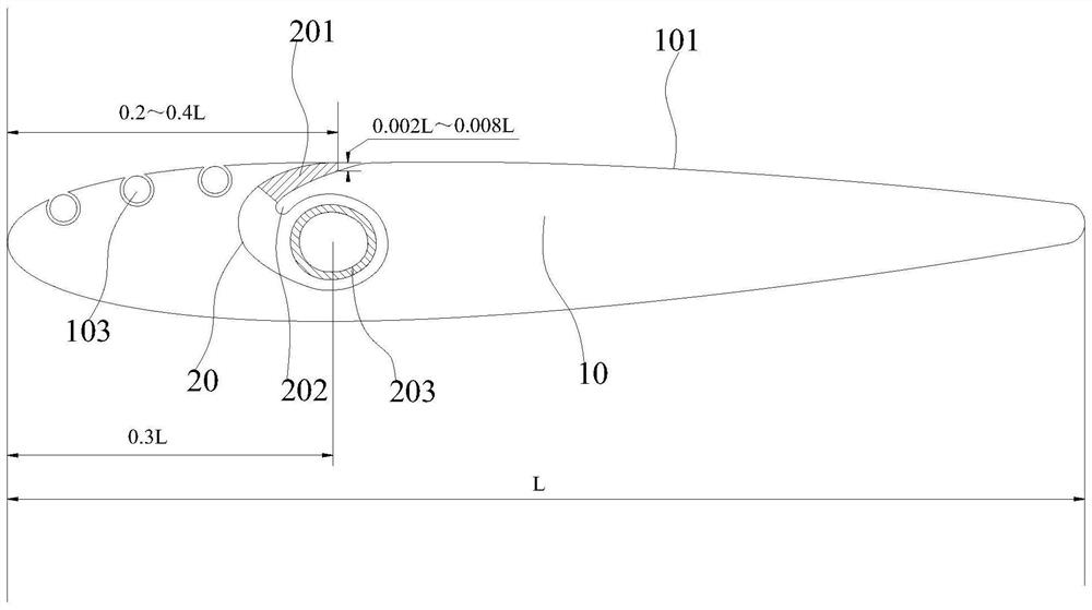
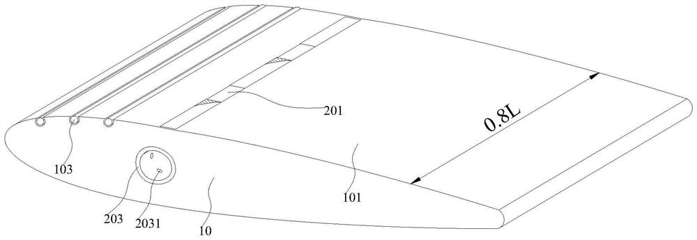
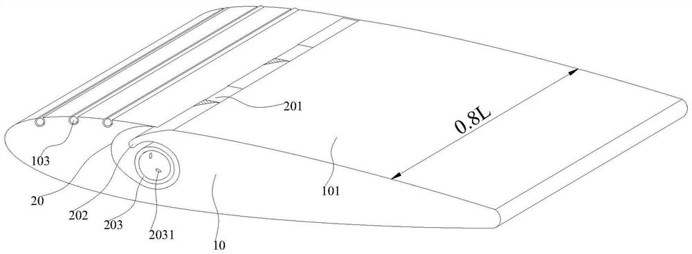
[0063] see Figure 1-19 , in the embodiment of the present invention, a wall-rolling blade with an active jet structure includes an airfoil body 10. The present invention takes the NACA0015 airfoil as an example, and the actual structure of the present invention can be applied to various airfoils. Such as figure 1 figure 2 image 3 As shown, taking the chord length of the airfoil body 10 as L and the airfoil span length as 0.8L, the airfoil body 10 is prov...


PUM


Abstract

The invention discloses a wall surface rolling-type blade with an active jet structure. The wall surface rolling-type blade comprises a wing-shaped body, wherein an active jet cavity recessed into the wing-shaped body from a suction surface is formed in the wing-shaped body in the extension direction; an opening, formed in the suction surface, of the active jet cavity serves as a jet outlet; a jet inlet penetrating through the wing end on one side of the wing-shaped body is formed in the active jet cavity in the extension direction, and communicates with an active jet source; a rectifying tip positioned between the jet inlet and the jet outlet as well as used for prolonging the fluid flow path is recessed into the active jet cavity; and in the fluid flow direction, the open area in the active jet cavity is gradually reduced. According to the wall surface rolling-type blade, the area of an upstream vortex region of the jet outlet is reduced, so that the downstream vortex region of the jet outlet can move down, the flow separation capacity of the wing-type suction surface can be restrained, and a separation point can get closer to the tail edge of the wing-type suction surface; and compared with a common active jet structure, the wall surface rolling-type blade has the advantages that the negative pressure area can be larger, the cavitation phenomenon can be prevented and the lift coefficient of the wing-type suction surface can be obviously improved.

Description

technical field [0001] The invention relates to the field of fluid machinery, in particular to a wall rolling blade with an active jet structure. Background technique [0002] The airfoil is the basic structure in the field of fluid machinery, and has been widely used in the fields of airfoils, propeller airfoils, wind power blade cross-section airfoils, and tidal energy power blade airfoils in the aviation field. With the rapid development of science and technology and fluid machinery industry, especially with the expansion of application fields, such as tidal power generation, marine water jet propulsion, underwater vehicles and other hydraulic machinery widely used, people are no longer satisfied with the traditional The dynamic performance provided by the wing puts higher and higher requirements on the performance of the airfoil. As the density and viscosity of the fluid medium change, resulting in the change of Reynolds number and Strouhal number of the flow around, th...

Claims


Application Information

Patent Timeline
Patent Type & Authority Applications(China)
IPC IPC(8): F01D5/14
CPCF01D5/147
Inventor 李晓俊燕浩苏晓珍马培勇祁风雷朱双四朱祖超
Owner ZHEJIANG SCI-TECH UNIV
Why Eureka
Eureka Blog
Learn More