Preparation method and preparation device of metal niobium nanopowder

A nano-powder and preparation device technology, applied in nanotechnology, nanotechnology, nanotechnology for materials and surface science, etc., can solve problems such as unfavorable industrial production, high preparation cost, low preparation yield, etc. The effect of lower product price and simple equipment operation

Inactive Publication Date: 2021-11-05
和超高装(中山)科技有限公司
View PDF11 Cites 1 Cited by
  • Summary
  • Abstract
  • Description
  • Claims
  • Application Information

AI Technical Summary

Problems solved by technology

[0004] In order to solve the problems of low preparation yield, high preparation cost and unfavorable industrial production in the existing method for preparing metallic niobium nanopowder, the present invention further provides a preparation method and preparation device for metallic niobium nanopowder;

Method used


Image

  • Preparation method and preparation device of metal niobium nanopowder
  • Preparation method and preparation device of metal niobium nanopowder
  • Preparation method and preparation device of metal niobium nanopowder

Examples


specific Embodiment approach 1

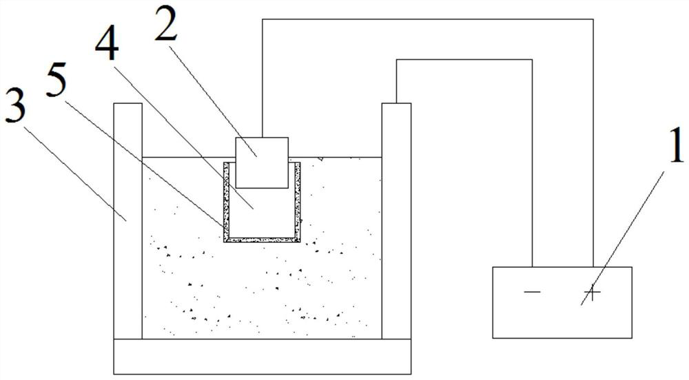
[0028] Specific implementation mode one: refer to Figure 1 to Figure 4 Describe this embodiment mode, this embodiment mode provides a kind of preparation device of metal niobium nanopowder, it is characterized in that: described preparation device comprises adjustable DC power supply 1, fixture 2 and reaction vessel 3, fixture 2 connects adjustable DC power supply through wire The positive pole of the power supply 1 is connected, and the reaction vessel 3 is connected with the negative pole of the adjustable DC power supply 1 through a wire;

[0029] The adjustable DC power supply 1 is connected to an oscilloscope, and the oscilloscope is used to analyze the waveform of the power supply, and a rectification component is arranged between the positive pole of the adjustable DC power supply 1 and the fixture 2;

[0030] The material of the clamp 2 is the same as that of the workpiece to be processed.

[0031] In this embodiment, the reaction vessel 3 is provided with a temperat...

specific Embodiment approach 2

[0032] Specific implementation mode two: refer to Figure 1 to Figure 4 Describe this embodiment. This embodiment is to further limit the rectifying component described in the first specific embodiment. In this embodiment, the rectifying component between the positive pole of the adjustable DC power supply 1 and the clamp 2 is a diode. The diode is connected in series between the positive pole of the adjustable DC power supply 1 and the fixture 2 . Other compositions and connection methods are the same as those in Embodiment 1.

specific Embodiment approach 3

[0033] Specific implementation mode three: refer to Figure 1 to Figure 4 Describe this embodiment. This embodiment is to further limit the rectifying component described in the second specific embodiment. In this embodiment, the rectifying component between the positive pole of the adjustable DC power supply 1 and the clamp 2 is a capacitor, and the capacitor is connected in parallel At both ends of the workpiece to be processed, one end of the capacitor is connected to the fixture 2 , and the other end of the capacitor is connected to the reaction container 3 . Other compositions and connection methods are the same as those in the second embodiment.

[0034] Combined with the description in the second and third embodiments, the waveform of the original power supply is analyzed by an oscilloscope, and it is found that the rectification effect of the power waveform is not good, and the output DC waveform is unstable. The method improves the rectified waveform to meet the proc...


PUM


Abstract

The invention discloses a preparation method and a preparation device of metal niobium nanopowder, belongs to the field of metal processing, and provides the preparation method and the preparation device of the metal niobium nanopowder in order to solve the problems that an existing preparation method of the metal niobium nanopowder is low in preparation yield, high in preparation cost and not beneficial to industrial production. Power supply output waveforms and power supply parameters can be controlled through information fed back by an oscilloscope, and the dynamic characteristic of power supply discharge is improved by combining the control of components and temperature of a processing medium solution, so that the purpose of accurately controlling the arc discharge intensity on the surface of a workpiece is achieved, the electric arc is controlled to discharge from the nanometer level to the micrometer level according to requirements, it is ensured that powder from the nanometer level to the micrometer level can be generated when a pure metal niobium plate is bombarded by the electric arc every time, the nanometer-level metal niobium powder can be attached to the surface of the pure metal niobium plate, and later recovery is facilitated.

Description

technical field [0001] The invention belongs to the field of metal processing, and in particular relates to a preparation method and a preparation device of metallic niobium nanopowder. Background technique [0002] Nano-metal powders have important applications in many fields, and the preparation methods of nano-metal powders have also developed rapidly, from gas-phase methods, liquid-phase methods, and solid-phase methods to laser methods, plasma methods, and metal spray combustion methods. These methods all have the problems of low output and high cost; the price of the produced powder products is high (the price of nano-metal powder is usually dozens of times that of ordinary metal powder), which seriously restricts the application and promotion of nano-metal powder. [0003] Due to the contraction of lanthanide, niobium has extra electrons, and the metal bond of niobium becomes stronger, so it has a higher melting point and boiling point and a larger atomic enthalpy, hi...

Claims


Application Information

Patent Timeline
Patent Type & Authority Applications(China)
IPC IPC(8): B22F9/14B22F1/00B82Y30/00
CPCB22F9/14B82Y30/00
Inventor 丁睿杨子酉何琳
Owner 和超高装(中山)科技有限公司
Why Eureka
Try Eureka