Flexible power tracking control method of photovoltaic power generation unit and application thereof

A technology of photovoltaic power generation and power tracking, which is used in photovoltaic power generation, control/adjustment system, regulating power variables and other directions. It can solve the problems of increased the cost of heat dissipation device, the temperature increase of subway traction power supply systems, to achieve extended life, reduce waste, reduce Cost effect

Active Publication Date: 2021-11-05
SOUTHWEST JIAOTONG UNIV
View PDF8 Cites 3 Cited by
  • Summary
  • Abstract
  • Description
  • Claims
  • Application Information

AI Technical Summary

Problems solved by technology

However, the use of braking resistors to consume electric energy will increase the temperature of the subway traction power supply system, and the use of cooling devices will increase the cost

Method used


Image

  • Flexible power tracking control method of photovoltaic power generation unit and application thereof
  • Flexible power tracking control method of photovoltaic power generation unit and application thereof
  • Flexible power tracking control method of photovoltaic power generation unit and application thereof

Examples


Embodiment 1

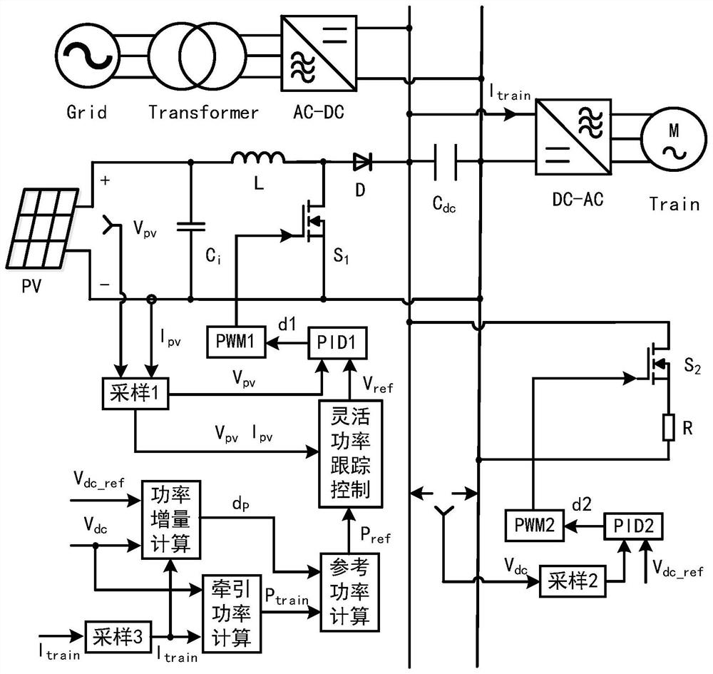
[0038] like figure 1 , the specific method is:

[0039] Step 1: Initialize parameters. Specifically include setting: the upper and lower limits of the DC bus voltage, the reference voltage of the DC bus, the sampling period of the flexible power tracking, the initial reference voltage of the photovoltaic array and other parameters.

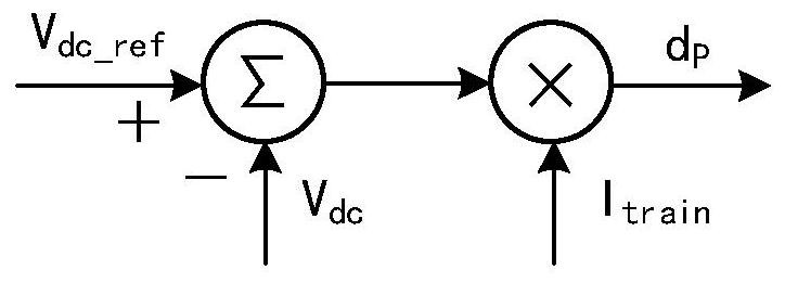
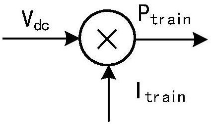
[0040] Step 2: Calculate the power reference value of photovoltaic power generation. First, the DC bus voltage is collected, the difference between the bus voltage and the corresponding reference value is calculated, and the power increment is calculated by combining the voltage difference and the input current of the locomotive. Then, the traction power of the locomotive is calculated through the bus voltage and the input current of the locomotive. Finally, the power needed to be provided by the traction power supply system is calculated by combining the power increment and the traction power of the locomotive, which is used as a power reference...

Embodiment 2

[0058] like Figure 9 As shown, the difference from the first embodiment is that the system controlled in this example is a DC microgrid system. Compared with Embodiment 1, the system of this embodiment can be applied to remote areas without power grids where power supply is inconvenient. In addition to the DC system in the above embodiments, the present invention can also be used in other rail traction power supply systems, AC microgrid systems and other systems including photovoltaic power generation units.

Embodiment 3

[0060] like Figure 10 As shown, the difference from Embodiment 1 is that the subway traction power supply system of this example consists of a high-voltage power grid, a transformer, a traction substation, a photovoltaic array, a DC-DC converter, a locomotive, a supercapacitor, and a bidirectional DC-DC converter composition. Among them, the bidirectional flow of energy of the supercapacitor is realized by controlling the bidirectional DC-DC converter through the inner voltage loop and the outer current loop. Compared with Embodiment 1, the system of this example can use the supercapacitor to balance the power difference between the photovoltaic array and the locomotive, and use the supercapacitor to release energy when the bus voltage of the catenary decreases; Capacitors absorb excess energy and reduce energy waste. In addition to the subway traction power supply system in the above embodiments, the present invention can also be used in a subway traction power supply syst...


PUM


Abstract

The invention discloses a flexible power tracking control method of a photovoltaic power generation unit and application thereof. The photovoltaic power generation unit is connected to the DC bus through the DC-DC converter, and the load is connected to the DC bus. According to the control method, the reference power and the output power of the photovoltaic power generation unit are judged, the working state of the photovoltaic power generation unit is selected as an MPPT mode or a constant power tracking mode, the output of the photovoltaic power generation unit is controlled in real time, and the DC bus voltage is adjusted. The method is suitable for occasions where the illumination intensity and the load power change continuously. When the photovoltaic power generation unit is applied to a traction power supply system and a micro-grid system, the use of a brake resistor and a heat dissipation device can be reduced, the cost is reduced, the capacity of other voltage stabilizing devices such as an energy storage device can be reduced, and the service life of the energy storage device is prolonged.

Description

technical field [0001] The invention relates to the technical field of new energy power generation, in particular to a flexible power tracking control method of a photovoltaic power generation unit and its application. Background technique [0002] With the continuous increase of urban population, subway has become an indispensable means of transportation in people's life. At the same time, with the rapid growth of the total mileage of rail transit operations, the power consumption of the subway is huge, and the problems of energy depletion and environmental pollution have emerged. Therefore, new energy has gradually entered the public's field of vision. Among them, solar energy, which is clean and easy to use, stands out among many new energy sources. In recent years, research on the application of new energy to urban rail transit has attracted much attention. The use of photovoltaic power generation in the subway traction power supply system can not only solve part of t...

Claims


Application Information

Patent Timeline
Patent Type & Authority Applications(China)
IPC IPC(8): G05F1/67
CPCG05F1/67Y02E10/56
Inventor 薛宁周国华毕强
Owner SOUTHWEST JIAOTONG UNIV
Why Eureka
Try Eureka