Eureka AIR delivers breakthrough ideas for toughest innovation challenges, trusted by R&D personnel around the world.

Push-pull optical amplifier

An optical amplifier and fiber amplifier technology, which is applied to semiconductor amplifier structures, lasers, laser components, etc., can solve problems such as the decline of extinction ratio, and achieve the effect of suppressing gain saturation, small magnification, and improving signal-to-noise ratio.

Active Publication Date: 2021-11-05
NANJING HENGGAO OPTO ELECTRONICS RES INST CORP
View PDF5 Cites 0 Cited by
  • Summary
  • Abstract
  • Description
  • Claims
  • Application Information

AI Technical Summary

Problems solved by technology

[0008] The purpose of the present invention is to provide a push-pull optical amplifier to solve the problem of suppressing the noise of the optical amplifier and solving the problem of the decrease of the extinction ratio caused by the gain saturation

Method used


Image

  • Push-pull optical amplifier
  • Push-pull optical amplifier
  • Push-pull optical amplifier

Examples


Embodiment 1

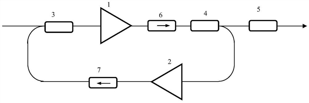
[0069] see Figure 1-3 , the main optical amplifying unit 1 and the auxiliary optical amplifying unit 2 are connected end to end to form an optical ring cavity with gain, thus becoming a laser.

[0070] Two optical amplifying units push-pull work, that is, when the main optical amplifying unit 1 is in the amplifying state, the auxiliary optical amplifying unit 2 is in a state close to locking; and when the auxiliary optical amplifying unit 2 is in the amplifying state, the main optical amplifying unit 1 is The amplified signal light is in a near-blocked state.

[0071] In order to set the wavelength to be amplified as λ 1 The optical signal is amplified, and a wavelength division multiplexer 3 and a wavelength division multiplexer 4 are respectively inserted between the main optical amplification unit 1 and the auxiliary optical amplification unit 2 .

[0072] In order to ensure that the resonant cavity formed by the push-pull optical amplifier can work in one direction, a f...

Embodiment 2

[0076] see Figure 1-3 , the main optical amplifying unit 1 and the auxiliary optical amplifying unit 2 are connected end to end to form an optical ring cavity with gain, thus becoming a laser.

[0077] Two optical amplifying units push-pull work, that is, when the main optical amplifying unit 1 is in the amplifying state, the auxiliary optical amplifying unit 2 is in a state close to locking; and when the auxiliary optical amplifying unit 2 is in the amplifying state, the main optical amplifying unit 1 is The amplified signal light is in a near-blocked state.

[0078] In order to set the wavelength to be amplified as λ 1 The optical signal is amplified, and a wavelength division multiplexer 3 and a wavelength division multiplexer 4 are respectively inserted between the main optical amplification unit 1 and the auxiliary optical amplification unit 2 .

[0079] In order to ensure that the resonant cavity formed by the push-pull optical amplifier can work in one direction, a f...

Embodiment 3

[0084] see Figure 1-3 , the main optical amplifying unit 1 and the auxiliary optical amplifying unit 2 are connected end to end to form an optical ring cavity with gain, thus becoming a laser.

[0085] Two optical amplifying units push-pull work, that is, when the main optical amplifying unit 1 is in the amplifying state, the auxiliary optical amplifying unit 2 is in a state close to locking; and when the auxiliary optical amplifying unit 2 is in the amplifying state, the main optical amplifying unit 1 is The amplified signal light is in a near-blocked state.

[0086] In order to set the wavelength to be amplified as λ 1 The optical signal is amplified, and a wavelength division multiplexer 3 and a wavelength division multiplexer 4 are respectively inserted between the main optical amplification unit 1 and the auxiliary optical amplification unit 2 .

[0087] In order to ensure that the resonant cavity formed by the push-pull optical amplifier can work in one direction, a f...


PUM


Abstract

A push-pull optical amplifier disclosed by the present invention comprises a main optical amplification unit and an auxiliary optical amplification unit which are connected end to end, work in a push-pull manner, and form an optical annular cavity with gain. The amplification factor of a low-power small signal to be amplified is small by adjusting the working points, and the amplification factor of a high-power large signal to be amplified is large. When the push-pull optical amplifier works with the small signal, the auxiliary light amplification unit works in a large gain state, so that the working points of the main light amplification unit are effectively stabilized, the light level stability of an output light signal is ensured, and the random fluctuation caused by the spontaneous radiation noise is effectively inhibited; when the push-pull optical amplifier works with the large signal, the auxiliary light amplification unit works in a small gain state, the gain saturation phenomenon of the main light amplification unit is effectively reduced, the amplification factor is larger than the amplification factor of the small signal, and the amplitude extinction ratio of an output light signal is improved.

Description

technical field [0001] The invention belongs to the technical field of optical fiber communication, and in particular relates to a push-pull optical amplifier. Background technique [0002] Optical amplifiers are the most basic devices for optical communication systems, optical sensing systems, and optical signal processing, and have been commercialized in large quantities. Optical amplifiers include lumped amplifiers and distributed amplifiers. Among them, lumped amplifiers are mainly fiber amplifiers and semiconductor optical amplifiers. Fiber amplifiers include erbium-doped fiber amplifiers, ytterbium-erbium co-doped fiber amplifiers, and fiber amplifiers doped with other elements. . [0003] From a practical point of view, it is divided into power amplifiers, low-noise preamplifiers, and repeater amplifiers. [0004] The basic principle of all amplifiers is based on the amplification of homomorphic photons formed by the stimulated radiation of photons in the gain mediu...

Claims


Application Information

Patent Timeline
Patent Type & Authority Applications(China)
IPC IPC(8): H01S3/067H01S5/50G02F1/39
CPCH01S3/06754H01S3/06758H01S5/50H01S5/5027G02F1/39
Inventor 吴重庆王健尚超
Owner NANJING HENGGAO OPTO ELECTRONICS RES INST CORP
Why Eureka
Eureka Blog
Learn More