

Plasma tail gas treatment equipment
An exhaust gas treatment and plasma technology, applied in gas treatment, separation method, dispersed particle separation, etc., can solve the problems of reducing the service life of internal components, reducing the effect of exhaust gas treatment, and the influence of components, so as to prolong the service life and improve the convenience. , to ensure the effect of dryness
- Summary
- Abstract
- Description
- Claims
- Application Information
AI Technical Summary
Problems solved by technology
Method used
Image

Examples
Embodiment 1
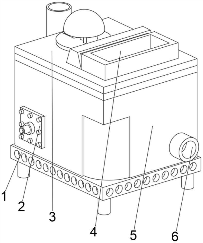
[0040] see Figure 1-6 , the present invention provides a technical solution: a plasma tail gas treatment equipment, including a fixed base 1, a processing device 5 is fixedly connected to the top of the fixed base 1, a plasma generator 2 is arranged on the left side of the front bottom of the processing device 5, and the plasma The back of the generator 2 runs through the processing device 5 and extends to the inside of the processing device 5. The bottom of the right outer wall of the processing device 5 is connected with an air outlet pipe 6. The top of the processing device 5 is provided with a top cover 3, and the top right side of the top cover 3 is provided There are sensors 4.
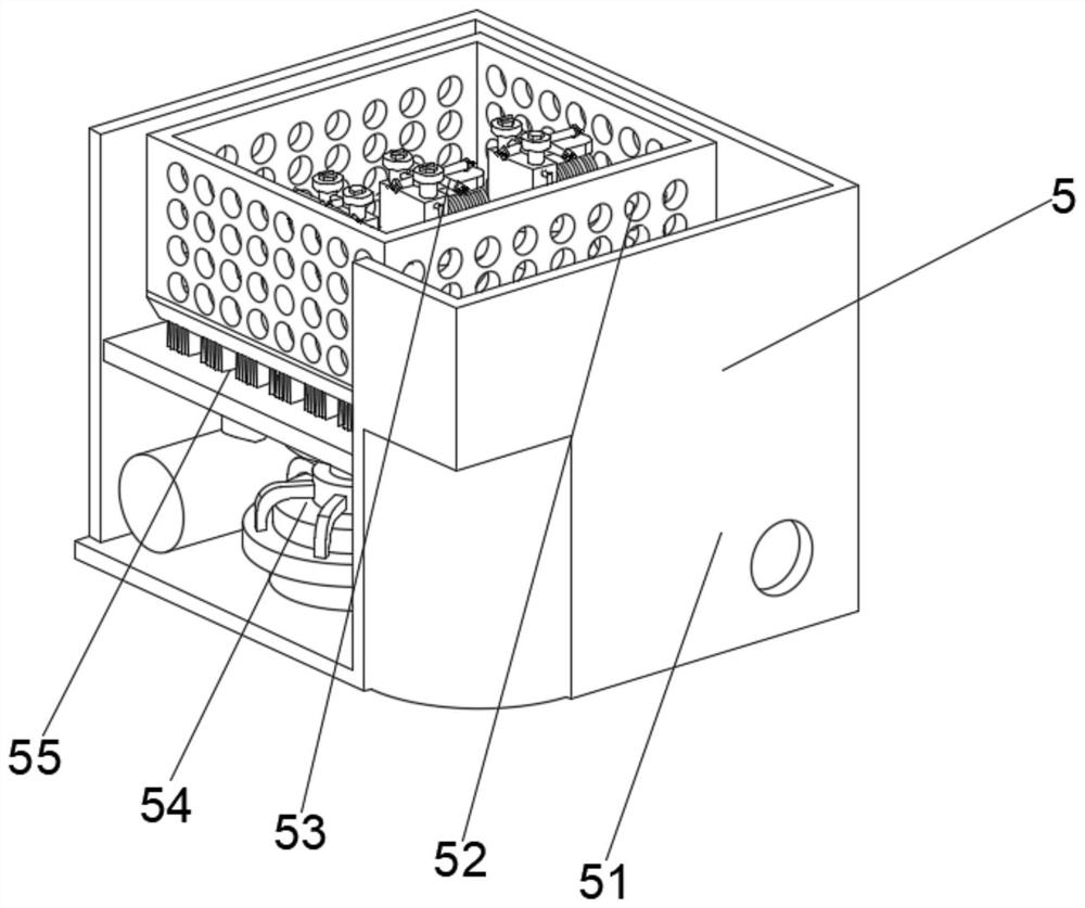
[0041] Wherein, the treatment device includes an exhaust gas treatment box 51 at 5, a purification mechanism 54 is arranged at the middle position of the inner cavity bottom of the exhaust gas treatment box 51, and a plasma connector 55 is arranged on the top of the purification mechanism 54, a...
Embodiment 2
[0047] see Figure 1-6 , on the basis of Embodiment 1, the present invention provides a technical solution: a method for using plasma tail gas treatment equipment, characterized in that: Step 1: Fix the equipment, and connect the intake pipe of the processing device 5 with the exhaust gas The storage pipeline is connected, the plasma generator 2 is connected to the power supply, and the plasma generator 2 is inserted into the processing device 5 as a whole;
[0048] Step 2: When the exhaust gas enters the device, it is energized through the plasma connector 55 to work, and the gas processed by the filter box 52 and the purification mechanism 54 passes through the plasma connector 55, and the internal circulation chamber generated by the filter box 52 and the protection mechanism 53 is carried out internally. waste gas recycling;
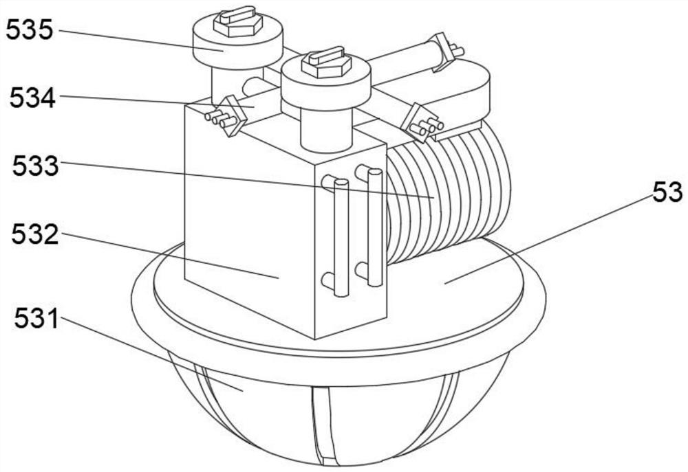
[0049] Step 3: Generate a control chamber for controlling the gas flow rate through the circulation pipeline 534 and the flow rate controller 535, ...
PUM
 Abstract
Description
Claims
Application Information