Multi-level photovoltaic inverter

A photovoltaic inverter, multi-level technology, applied in photovoltaic power generation, electrical components, circuit devices, etc., can solve the problems of high power loss, reduced conversion efficiency, poor output power quality, etc., to improve work reliability, reduce Small size and weight, the effect of improving conversion efficiency

Pending Publication Date: 2021-11-09
深圳崧盛创新技术有限公司
View PDF0 Cites 7 Cited by
  • Summary
  • Abstract
  • Description
  • Claims
  • Application Information

AI Technical Summary

Problems solved by technology

[0003] The three-phase inverter circuit usually uses the traditional two-level inverter topology, which requires the use of higher withstand voltage power switching devices, and there is a large power loss, thereby reducing the system conversion efficiency. At the same time, the output filter inductor has a large volume, which further reduces the conversion efficiency. And increase the cost, and the output power quality is also relatively poor
The circuit structure of the diode-clamped or neutral-grounded three-level topology (I3) is relatively simple, but the number of power switch tubes is large, and the system control becomes more complicated. At the same time, the clamping diode increases the total loss and reduces the conversion efficiency
Its improved (A New Single-PhaseΠ-Type 5-Level Inverter Using 3-TerminalSwitch-Network, IEEE Industrial Electronics 2016 Volume 63 Issue 11) inverter midpoint output voltage is five levels, but the control used Strategies are too complex and reactive power cannot be exported
[0004] In general five-level, seven-level and other more level methods, the higher level of the output midpoint voltage can reduce the power loss of the switching device, but the power device increases geometrically, and its control becomes more complicated. Therefore, the photovoltaic inverter Inverters, frequency converters, uninterruptible power supplies, etc. usually only use three-level topologies
In addition, some high-efficiency multi-level topologies proposed in recent years are patented by European and American countries, which has caused serious technical barriers to the promotion and application of new energy power generation in China.

Method used


Image

  • Multi-level photovoltaic inverter
  • Multi-level photovoltaic inverter
  • Multi-level photovoltaic inverter

Examples


Embodiment Construction

[0029] Below, the present invention will be further described in conjunction with the accompanying drawings and specific implementation methods. It should be noted that, under the premise of not conflicting, the various embodiments described below or the technical features can be combined arbitrarily to form new embodiments. .

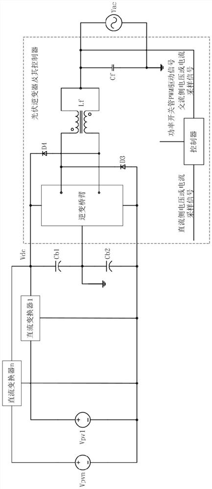
[0030] Multi-channel MPPT two-stage multi-level photovoltaic inverter topology, such as figure 2 As shown, the multi-channel MPPT function is realized by 1 to n multiple DC converters, where Vpv1, ..., Vpvn are the output voltages of photovoltaic modules or photovoltaic strings, and Vdc is the output voltage of DC converters, that is, the DC input voltage of the inverter . Photovoltaic inverter is mainly composed of inverter bridge arm, freewheeling diode, double-winding anti-phase coupling split inductor, output filter capacitor, controller, DC bus voltage dividing capacitor, and several DC converters. Among them, Vac is AC output or public power gr...


PUM


Abstract

The invention provides a multi-level photovoltaic inverter. The multi-level photovoltaic inverter is mainly composed of an inverter bridge arm, a fly-wheel diode, a double-winding anti-phase coupling split inductor and a controller. The inverter bridge arm comprises a power switch tube and a power diode, and a coupling inductor is arranged between the bridge arms to avoid the direct connection risk of the inverter bridge arm. The controller samples alternating current and direct current voltage and current signals, and correspondingly adjusts input voltage and output current. A multi-carrier interleaving modulation strategy is adopted, and the inversion midpoint output voltage is five-level and can be output in a reactive power mode. The inverter has the unique advantages of multi-level, high efficiency, high reliability, reactive power output and the like, and can be widely applied to various one-way and two-way direct current-alternating current power converters.

Description

technical field [0001] The invention relates to the field of photovoltaic technology, in particular to a multilevel photovoltaic inverter. Background technique [0002] The DC power output by photovoltaic modules or strings changes randomly, and the inverter converts it into AC power with the same frequency and phase as the AC grid. The DC voltage of photovoltaic modules is inversely proportional to the ambient temperature, and the DC input voltage is low in a high-temperature environment, so a DC-DC conversion circuit (DC / DC) can be added, and a boost circuit (Boost) is generally used to form a two-stage three-phase inverter Transformer such as figure 1 shown. When the DC input voltage is higher than the peak value of the AC output voltage, the boost circuit does not work, and the DC input directly enters the inverter circuit through Lb, Db or additional bypass diodes, that is, the voltages at both ends of Cin and Cb are equal, and the DC / AC circuit realizes Inverted AC ...

Claims


Application Information

Patent Timeline
Patent Type & Authority Applications(China)
IPC IPC(8): H02M7/487H02M7/493H02J3/38
CPCH02M7/487H02M7/493H02J3/381H02J2300/24Y02E10/56
Inventor 袁源兰
Owner 深圳崧盛创新技术有限公司
Why Eureka
Try Eureka