Waveguide invariant estimation method based on deep sea vertical array

A waveguide invariant, vertical array technology, applied in radio wave measurement systems, measurement devices, sound wave re-radiation and other directions, can solve problems such as small implementation significance, and achieve the effect of simple method, low computational complexity, and saving computational time.

Pending Publication Date: 2021-11-19
NAT INNOVATION INST OF DEFENSE TECH PLA ACAD OF MILITARY SCI
View PDF9 Cites 1 Cited by
  • Summary
  • Abstract
  • Description
  • Claims
  • Application Information

AI Technical Summary

Problems solved by technology

In addition, the method of extracting waveguide invariants based on interference fringe beamforming is only applicable to the case where the angle between the target azimuth and the array's transverse direction is less than 30°, which is of little significance in engineering

Method used


Image

  • Waveguide invariant estimation method based on deep sea vertical array
  • Waveguide invariant estimation method based on deep sea vertical array
  • Waveguide invariant estimation method based on deep sea vertical array

Examples


Embodiment Construction

[0043] The present invention will be described in detail below with reference to the accompanying drawings and examples.

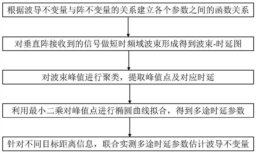
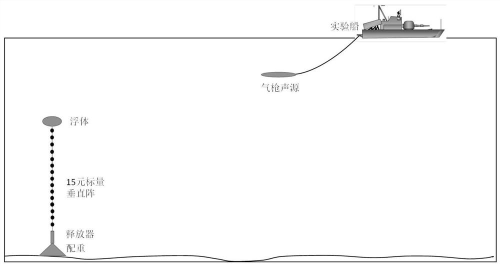
[0044] The present invention provides a figure 1 It is a flow chart of the method for estimating waveguide invariants based on deep-sea vertical arrays in the present invention, based on which, waveguide invariants at different distances are estimated. In this example, the vertical hydrophone line array deployed near the seabed is considered, the number of array elements is 15, the array element spacing is 7.5m, the equivalent depth of the vertical array is 4105.5m, and the sea depth is 4262m. The experimental ship towed the sound source of the air gun to make a uniform linear motion from near to far, and the moving speed was about 4 knots. The air gun emits a signal every 90s, the equivalent depth of the air gun is about 10m, and the sound source distance is about 5km-20km. The experimental equipment is deployed as figure 2 shown.

[0045]Taking the ...


PUM


Abstract

The invention discloses a waveguide invariant estimation method based on a deep sea vertical array, which relates to the technical field of underwater acoustic parameter estimation, can estimate waveguide invariants under two conditions of known and unknown target distances, and is simple and convenient. The waveguide invariant estimation method is characterized by comprising the following steps of: S1, establishing a function relationship among a waveguide invariant beta, a multipath time delay parameter bv, a signal arrival glancing angle theta, an arrival time delay t and a target distance R; S2, utilizing a target radiation sound signal received by a vertical hydrophone array deployed at a deep sea bottom, and carrying out short-time frequency domain beam forming processing on the target radiation sound signal to obtain a beam time delay diagram; S3, carrying out clustering on the wave beam time delay diagram and extracting a wave beam peak point and a corresponding time delay value; S4, carrying out curve fitting by using a least square method aiming at the head of the extracted wave beam peak so as to solve multipath time delay parameters; and S5, aiming at different target distance prior information, combining actual measurement multipath time delay parameters to estimate waveguide invariants.

Description

technical field [0001] The invention relates to the technical field of underwater acoustic parameter estimation, in particular to a method for estimating waveguide invariants based on deep-sea vertical arrays. Background technique [0002] There is a stable interference structure in the low-frequency sound field, which contains rich target motion information and marine environment information. Since the advent of the waveguide invariant theory in 1982, Chuprov has described the complex interference structure in the shallow sea sound field with only one scalar. After the proposal, researchers from various countries have conducted a lot of research on the waveguide invariance of the sound field from different angles. Brekhovskikh et al. briefly explained the waveguide invariant theory, and analyzed the space-frequency interference of the ocean acoustic field; Rouseff et al. believed that under the influence of the ocean environment, the waveguide invariant should be modeled as...

Claims


Application Information

Patent Timeline
Patent Type & Authority Applications(China)
IPC IPC(8): G01S15/58G01S15/42
CPCG01S15/58G01S15/42
Inventor 罗再磊郜永帅沈同圣刘峰
Owner NAT INNOVATION INST OF DEFENSE TECH PLA ACAD OF MILITARY SCI
Why Eureka
Try Eureka