

Organic waste gas treatment equipment for environmental protection engineering
Patent Information
- Authority / Receiving Office
- CN · China
- Current Assignee / Owner
- 深圳市鑫煜辉环保科技有限公司
- Publication Date
- 2021-11-23
- Estimated Expiration
- Not applicable · inactive patent
Smart Images
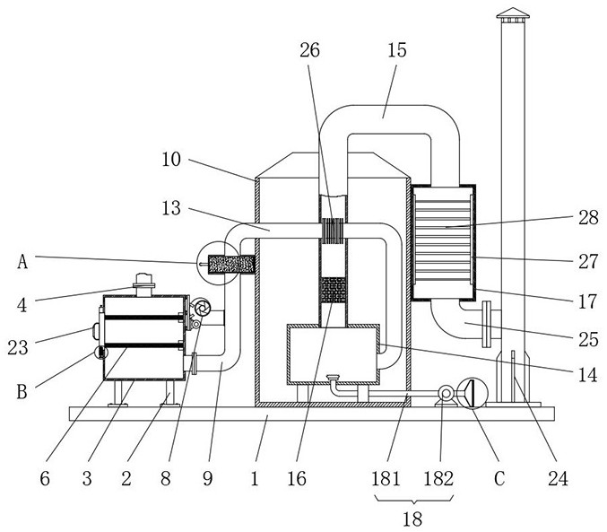
Figure 1 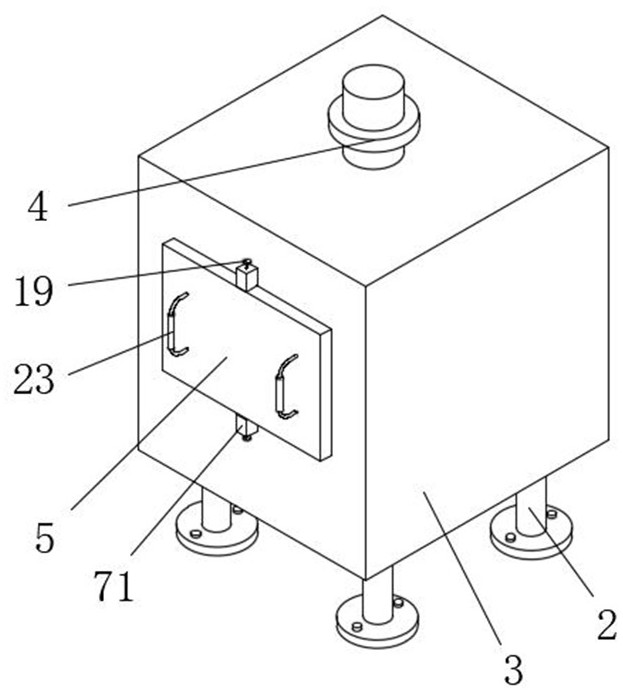
Figure 2 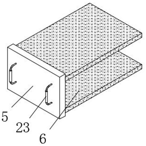
Figure 3
Abstract
Description
technical field
[0001] The invention relates to the technical field of environmental protection engineering, in particular to an organic waste gas treatment equipment used in environmental protection engineering. Background technique
[0002] Environmental protection engineering refers to projects specifically for environmental protection. Due to the environmental pollution caused by industrial development, based on a certain group of imagined goals, the application of relevant scientific knowledge and technical means, through the organized activities of a group of people, the problem of environmental pollution will be eliminated. Some projects to be dealt with, the contents of environmental protection projects mainly include air pollution prevention and control projects, water pollution prevention and control projects, solid waste treatment and utilization projects, and noise control projects, etc. The treatment of organic waste gas is included in air pollution prevention an...