Waste gas recovery method applied to soft-touch leather coating production

A leather coating and waste gas recovery technology, applied in the field of soft-touch leather coatings, can solve the problems of substandard waste gas temperature and poor cooling environment, and achieve the effects of improving cooling and increasing discharge.

Active Publication Date: 2021-11-26
瑞润化工(南通)有限公司
View PDF8 Cites 0 Cited by
  • Summary
  • Abstract
  • Description
  • Claims
  • Application Information

AI Technical Summary

Problems solved by technology

[0004] However, in the actual use process, the inventors found that improving the long-term use of the heat exchanger leads to the deterioration of the refrigeration environment inside, which in turn leads to the problem that the output exhaust gas temperature is not up to standard

Method used


Image

  • Waste gas recovery method applied to soft-touch leather coating production
  • Waste gas recovery method applied to soft-touch leather coating production
  • Waste gas recovery method applied to soft-touch leather coating production

Examples


Embodiment 1

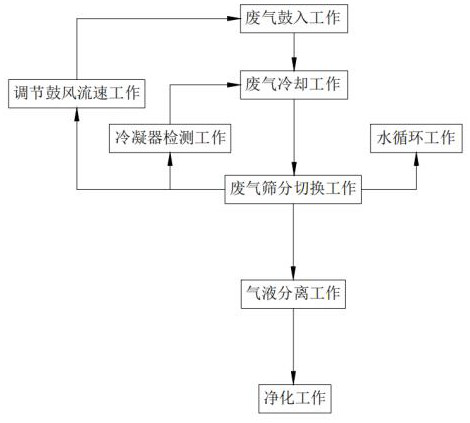
[0081] Such as figure 1 As shown, a method for recovering waste gas from the production of soft-touch leather coatings, including:

[0082] In the first step, the waste gas is blasted into the work, and the waste gas containing heat is blown into the heat exchanger 1b through the fan 1a;

[0083] The second step is exhaust gas cooling. The heat-containing exhaust gas performs preliminary cooling of the exhaust gas in the heat exchanger 1b. The exhaust gas is transported in an S shape under the action of the first rotating assembly 31a and the second rotating assembly 31b in the heat exchanger 1b. Inside, the condensed liquid is finally collected from the liquid outlet, and the exhaust gas passing through the heat exchanger 1b is transmitted to the three-way output;

[0084] The third step is to switch over the waste gas screening. When the temperature control accuracy meter detects that the temperature of the air flow output from the heat exchanger 1b is higher than a certain...

Embodiment 2

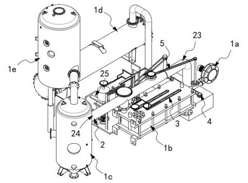
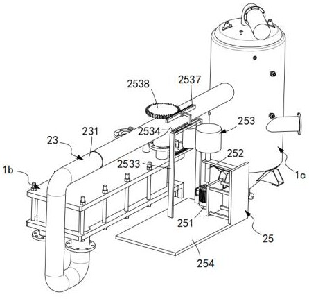
[0102] Such as figure 2 As shown, the industrial waste gas high-efficiency recovery system includes a fan 1a, a heat exchanger 1b, a rotary separator 1c, a cooling tower 1d, and a gas-liquid mixing tower 1e. The exhaust gas is directed to the switching mechanism 2 for automatic flow splitting, the cooling mechanism 3 arranged in the heat exchanger 1b and driven along the length direction of the heat exchanger 1b, and used to control the heat exchanger 1b and the rotary separator 1c The heat dissipation mechanism 4 for pre-cooling the water after internal heating, the water outlet 4a of the heat dissipation mechanism 4 is communicated with the cooling tower 1d and its water inlet 4b is communicated with the heat exchanger 1b;

[0103] The switching mechanism 2 includes a tee 21 arranged on the upper end of the heat exchanger 1b, a switching plate 22 installed in the center of the transition of the tee 21, one end communicates with the tee 21 and the other end communicates with...


PUM


Abstract

The invention relates to a waste gas recovery method applied to soft-touch leather coating production. The method comprises the following steps: 1, waste gas blowing-in work; 2, waste gas cooling work; 3, waste gas screening switching work; 4, air blowing flow speed adjusting work; 5, condenser detecting work; and 6, water circulation work which is synchronous with the step 3, wherein a fifth transmission assembly is driven by a driving mechanism, so that water with relatively high temperature in a water tank is rapidly stirred under the stirring action of a stirring assembly, the flow speed of the water in the water tank is increased, the water in the water tank is rapidly cooled, meanwhile, waste gas in a first connecting pipe is cooled by utilizing the water after heat loss; 7, gas-liquid separation work; and 8, purification work; the technical problem that the temperature of output waste gas does not reach the standard due to the fact that the refrigeration environment in a heat exchanger becomes poor when the heat exchanger is used for a long time is solved.

Description

technical field [0001] The invention relates to the technical field of soft-touch leather coatings, in particular to a method for recovering waste gas from production of soft-touch leather coatings. Background technique [0002] Leather coatings refer to coatings used to protect and decorate leather. Leather paint requires fast drying, good gloss, soft performance, and is not easy to crack when applied on the surface. Leather nitro paints of various colors are made of nitrocellulose and alkyd resin dissolved in volatile organic solvents, and added with pigments and enhancers. Made of plastic. Soft nitro varnish is a colloidal solution made of cellulose nitrate, long-oil acid resin and plasticizer dissolved in volatile organic solvents. It is used for scraping or spraying the surface of soft objects such as tape measure and leather. Polyurethane varnish can also be used on the surface of leather products. The paint has good water resistance, oil resistance and high gloss. ...

Claims


Application Information

Patent Timeline
Patent Type & Authority Applications(China)
IPC IPC(8): B01D53/78B01D5/00
CPCB01D53/78B01D53/002B01D5/00
Inventor 林易
Owner 瑞润化工(南通)有限公司
Why Eureka
Try Eureka