Multicore optical fiber and design method

A multi-core optical fiber and design method technology, applied in multi-core optical fiber, cladding optical fiber, light guide, etc., can solve problems such as ambiguity, and achieve the effects of increasing multiplicity, reducing pulse response width, and expanding transmission capacity

Active Publication Date: 2021-11-26
NIPPON TELEGRAPH & TELEPHONE CORP
View PDF7 Cites 1 Cited by
  • Summary
  • Abstract
  • Description
  • Claims
  • Application Information

AI Technical Summary

Problems solved by technology

[0022] However, Non-Patent Document 6 only discloses a description of the case where the core refractive index distribution (core radius, relative refractive index difference) is a specific value.
That is, the above-mentioned non-patent literature does not disclose an arbitrary multi-core structure (core refractive index distribution, core spacing, etc.) for obtaining random mode coupling, so there is a problem that a coupling-type multi-core fiber is adopted as an optical fiber for communication. It is still not clear which structure is appropriate

Method used


Image

  • Multicore optical fiber and design method
  • Multicore optical fiber and design method
  • Multicore optical fiber and design method

Examples


Embodiment approach 1

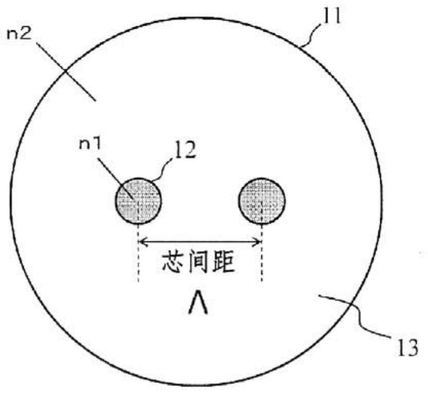
[0061] figure 1 It is a cross-sectional view of a multi-core optical fiber 11 having two cores. There is a core region 12 with a refractive index n1 and a cladding region 13 with a refractive index n2, n1>n2.

[0062] exist figure 1 In the structure, the condition of n1>n2 is realized by using pure quartz glass or quartz glass as the material of each region, and the quartz glass is added with germanium (Ge), aluminum (Al), phosphorus (P), etc. to increase the refractive index impurities, or impurities such as fluorine (F) and boron (B) that lower the refractive index. Also, let the core pitch be Λ.

[0063] When designing a coupling-type multi-core fiber, regarding the bending radius, as stipulated in the measurement of the cutoff wavelength in ITU-T, as an alternative to using a cable sample, an optical fiber wire with a bending radius of 140 mm is used, which means that in-line A bend with a bend radius of 140 mm is effectively generated in the cable, and when the optica...

Embodiment approach 2

[0103] In Embodiment 1, it was described that the core pitch required to obtain random coupling varies depending on the core structure such as Δ, but the coupling coefficient κ required to obtain random coupling is fixed. Here, according to Non-Patent Document 11 Figure 4 .16, the relationship between aκ / √Δ and Λ / a including the coupling coefficient κ can be expressed as a function of the normalized frequency V, and the constants A and B can be used, by

[0104] [number 5]

[0105]

[0106] express.

[0107] Here, assuming a step core, if the changes of A and B are calculated with respect to the V value, and the values ​​are obtained empirically, then as Figure 12 shown in Table 2. Figure 5 and Figure 6 The results of deriving the relationship between A and B and the V value from Table 2 are shown, respectively. according to Figure 5 and Figure 6 ,

[0108] A=f(V)=-8.7812+5.51V

[0109] B=f(V)=1.0027-1.188V.

[0110] Let κ required for random coupling be κc....

Embodiment approach 3

[0119] Here, it is calculated to what degree the amount of coupling becomes random coupling and the impulse response width can be reduced. Considering that the relay section sandwiched between optical amplifiers is generally more than 40km, the shape of the impulse response when the coupling amount is changed at a transmission distance of 40km is calculated, and the results are shown in Figure 7 . For ease of illustration, the DMD between modes is set to 1 ns / km.

[0120] At -50dB / m, there are pulses showing relatively high intensity at both ends, the width of which is 40ns, and becomes the same value as the cumulative DMD (1ns / km×40km). In the case of -40dB / m, the pulse intensity at both ends is reduced, but the pulse response width is the same as the accumulated DMD.

[0121] On the other hand, at a coupling amount of -30 dB / m or more, the impulse response shape is Gaussian. It can be seen that the shape of the impulse response is Gaussian when the inter-mode coupling is...


PUM

PropertyMeasurementUnit
diameteraaaaaaaaaa

Abstract

The purpose of the present invention is to provide a multicore structure for obtaining random mode coupling in the case of an arbitrarily defined core refractive index. This multicore optical fiber is an optical fiber in which two or more core regions are disposed with a minimum core spacing Lambda therebetween in a clad region having a smaller refractive index than the refractive index of the core, and is characterized in that the structure of the core is a structure having a single propagation mode, and the core structure and the core spacing are adjusted such that an intermode coupling coefficient between adjacent cores falls within a range of 0.73-120 m-1.

Description

technical field [0001] The present disclosure relates to a multi-core optical fiber. Background technique [0002] In fiber optic communication systems, the transmission capacity is limited due to nonlinear effects generated in the fiber or fiber melting. In order to alleviate these limitations, parallel transmission using a multi-core fiber having multiple cores in one fiber (Non-Patent Document 1), mode-multiplexing transmission using a multimode fiber having multiple propagation modes in a core ( Non-Patent Document 2), and a spatial multiplexing technique such as a multimode multi-core optical fiber (Non-Patent Document 3) in which multiple cores and mode multiplexing are combined. [0003] prior art literature [0004] Non-Patent Document 1: H.Takara et al., "1.01-Pb / s(12SDM / 222WDM / 456Gb / s) Crosstalk-managed Transmission with 91.4-b / s / Hz Aggregate SpectralEfficiency," in ECOC2012, paper Th. 3.C.1 (2012) [0005] Non-Patent Document 2: T.Sakamoto et al., "Differentia...

Claims


Application Information

Patent Timeline
Patent Type & Authority Applications(China)
IPC IPC(8): G02B6/02
CPCG02B6/02042G02B6/02009G02B27/0012
Inventor 坂本泰志中岛和秀和田雅树青笹真一山本贵司
Owner NIPPON TELEGRAPH & TELEPHONE CORP
Why Eureka
Try Eureka