In-furnace calcium spraying-based desulfurization method and device for flue gas produced during incineration of hazardous waste

A technology for incineration flue gas and desulfurization equipment, applied in separation methods, chemical instruments and methods, gas treatment, etc., can solve the problems of complex system management operations, large floor space, high production and operation costs, and achieve high reaction efficiency.

Pending Publication Date: 2021-11-30
SHANDONG ACAD OF ENVIRONMENTAL SCI CO LTD
View PDF0 Cites 0 Cited by
  • Summary
  • Abstract
  • Description
  • Claims
  • Application Information

AI Technical Summary

Problems solved by technology

[0005] Using the above-mentioned deacidification process, the acid gas removal rate can be above 99%, the deacidification efficiency is high, and the discharge of flue gas can be achieved; but a series of problems follow: (1) wet deacidification produces a large amount of The high-salt wastewater needs to be sent to the sewage treatment station to be treated and discharged up to the standard, and the production and operation costs are high; (2) The wet deacidification requires a large investment, occupies a large area, and the system management operation is complicated; (3) The wet deacidification The deacidification load of the acid section is relatively large, and a large amount of lye needs to be sprayed, and the operating cost is high. At the same time, the temperature of the flue gas after deacidification is about 60°C, which will cause great low-temperature corrosion to the subsequent induced draft fan and flue

Method used


Image

  • In-furnace calcium spraying-based desulfurization method and device for flue gas produced during incineration of hazardous waste
  • In-furnace calcium spraying-based desulfurization method and device for flue gas produced during incineration of hazardous waste
  • In-furnace calcium spraying-based desulfurization method and device for flue gas produced during incineration of hazardous waste

Examples


Embodiment Construction

[0032] In order to make the purpose, technical solutions and advantages of the embodiments of the present invention more clear, the technical solutions in the embodiments of the present invention will be clearly and completely described below in conjunction with the accompanying drawings in the embodiments of the present invention. Obviously, the described embodiments It is a part of embodiments of the present invention, but not all embodiments. Based on the embodiments of the present invention, all other embodiments obtained by persons of ordinary skill in the art without making creative efforts belong to the protection scope of the present invention.

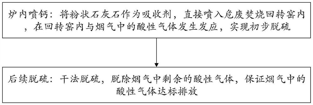
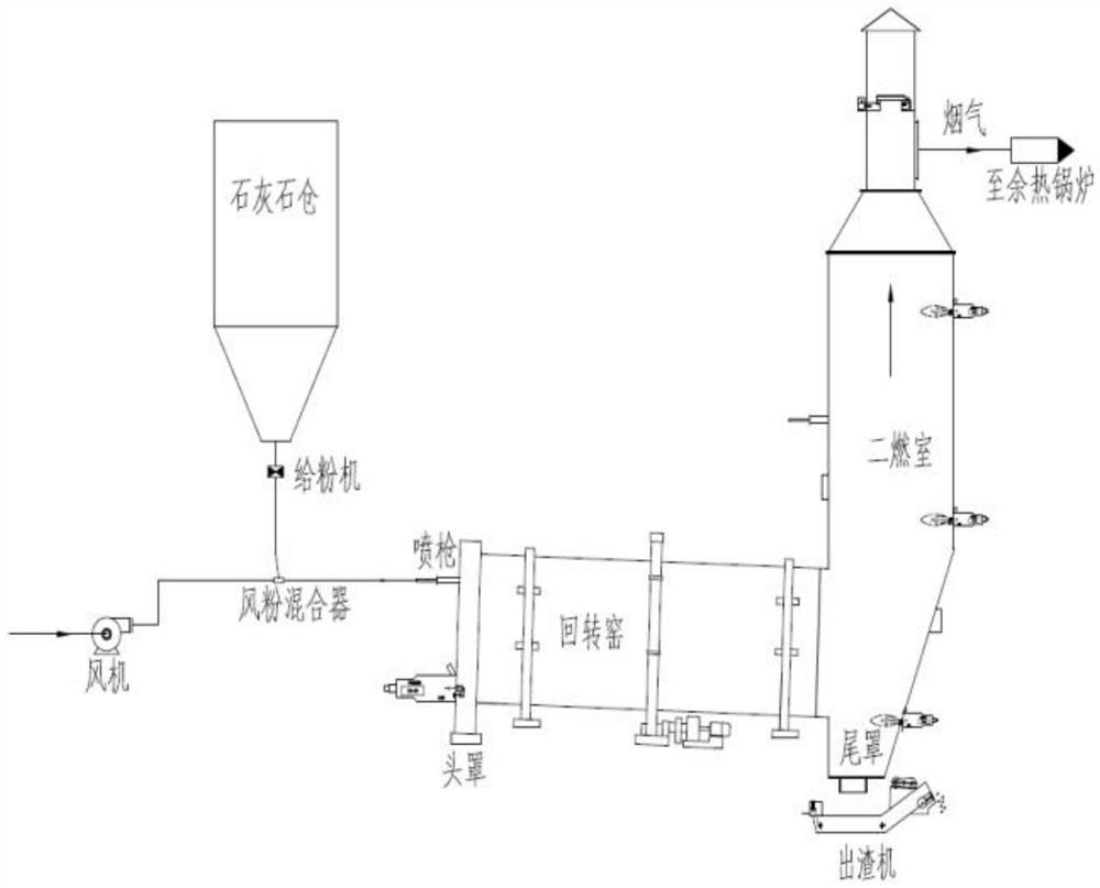
[0033] The present invention conducts in-depth and specific research on the mechanism, design, operation and other aspects of desulfurization by calcium spraying in furnaces of hazardous waste incineration systems.

[0034] The present invention provides a hazardous waste incineration flue gas desulfurization method based on c...


PUM

PropertyMeasurementUnit
lengthaaaaaaaaaa
diameteraaaaaaaaaa

Abstract

The invention relates to an in-furnace calcium spraying-based desulfurization method and device for flue gas produced during incineration of hazardous waste. The method comprises the following steps: in-furnace calcium spraying: directly spraying powdery limestone into a rotary kiln for hazardous waste incineration as an absorbent, and allowing the powdery limestone to react with acid gas in flue gas in the rotary kiln to realize preliminary desulfurization; and subsequent desulfurization: carrying out dry desulfurization to remove residual acid gas in the flue gas, wherein the acid gas in the flue gas is ensured to reach the standard before discharging. The device comprises the rotary kiln for hazardous waste incineration, a limestone powder feeding device, a powder feeder, a limestone bin, an air feeder, a spray gun, a bag-type dust collector and an air powder mixer. According to the in-furnace calcium spraying-based desulfurization method and device for flue gas produced during incineration of the hazardous waste, it can be guaranteed that the acid gas in the flue gas reaches the standard before being discharged; and meanwhile, a wet deacidification measure can be avoided, so the problem that deacidification wastewater is difficult to treat is solved.

Description

technical field [0001] The invention belongs to the technical field of flue gas deacidification of hazardous waste incineration, and in particular relates to a method and device for desulfurizing flue gas of hazardous waste incineration based on calcium spraying in a furnace. Background technique [0002] Hazardous waste incineration flue gas deacidification technology is to deacidify SO in the tail gas produced in the incineration process 2 Neutralization and adsorption treatment with HCl is to ensure that the pollutant indicators meet the requirements of the emission indicators stipulated in the national standards. Considering the complexity of the sources of hazardous waste and the fact that the national discharge standards will only become more and more stringent in the future, the current and future development should be considered in the design. The deacidification process used in common projects is a two-stage dry method + wet method Deacidification process. [0003...

Claims


Application Information

Patent Timeline
Patent Type & Authority Applications(China)
IPC IPC(8): B01D53/83B01D53/50B01D53/40
CPCB01D53/83B01D53/40B01D53/508B01D2258/0283B01D2251/404B01D2251/602
Inventor 杨国强杜鹏贾颖博刘宁王倩倩吕尚
Owner SHANDONG ACAD OF ENVIRONMENTAL SCI CO LTD
Why Eureka
Try Eureka