
3D printing assembled monolithic catalyst and preparation method thereof

A monolithic catalyst and 3D printing technology, which is applied in the direction of catalyst activation/preparation, oxidation reaction preparation, chemical instruments and methods, etc., can solve the problem that the scalability of the monolithic catalyst cannot be realized, the monolithic catalyst cannot be fixed, and the mechanical strength is insufficient and other issues, to achieve the effect of simple structure, easy design and manufacture, and reduced manufacturing cost

Active Publication Date: 2021-11-30
XI AN JIAOTONG UNIV
View PDF13 Cites 2 Cited by
  • Summary
  • Abstract
  • Description
  • Claims
  • Application Information

AI Technical Summary

Problems solved by technology

[0004] At present, there are some precedents for 3D printing monolithic catalysts. The Chinese patent (CN202011013321.7, name: a method for 3D printing monolithic catalysts) precisely manufactures the required A monolithic catalyst with a complex structure and optimized performance formed by a variety of materials, which cannot be achieved by traditional manufacturing processes
But this technology has the following disadvantages: 1) the protection of the monolithic catalyst, due to the shortcomings of the monolithic catalyst, such as insufficient mechanical strength and poor impact resistance, the phenomenon of fragmentation caused by the impact of the liquid and the collision of the stirring device during the experiment Occurs from time to time; 2) The controllability of the catalytic reaction is poor, the position of the monolithic catalyst cannot be fixed in the catalytic reaction, and the scalability of the monolithic catalyst cannot be realized, etc.

Method used


Image

  • 3D printing assembled monolithic catalyst and preparation method thereof
  • 3D printing assembled monolithic catalyst and preparation method thereof
  • 3D printing assembled monolithic catalyst and preparation method thereof

Examples


Embodiment 1

[0032] Embodiment 1, a kind of preparation method of 3D printing can assemble monolithic catalyst, comprises the following steps:

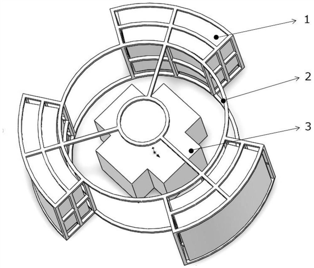
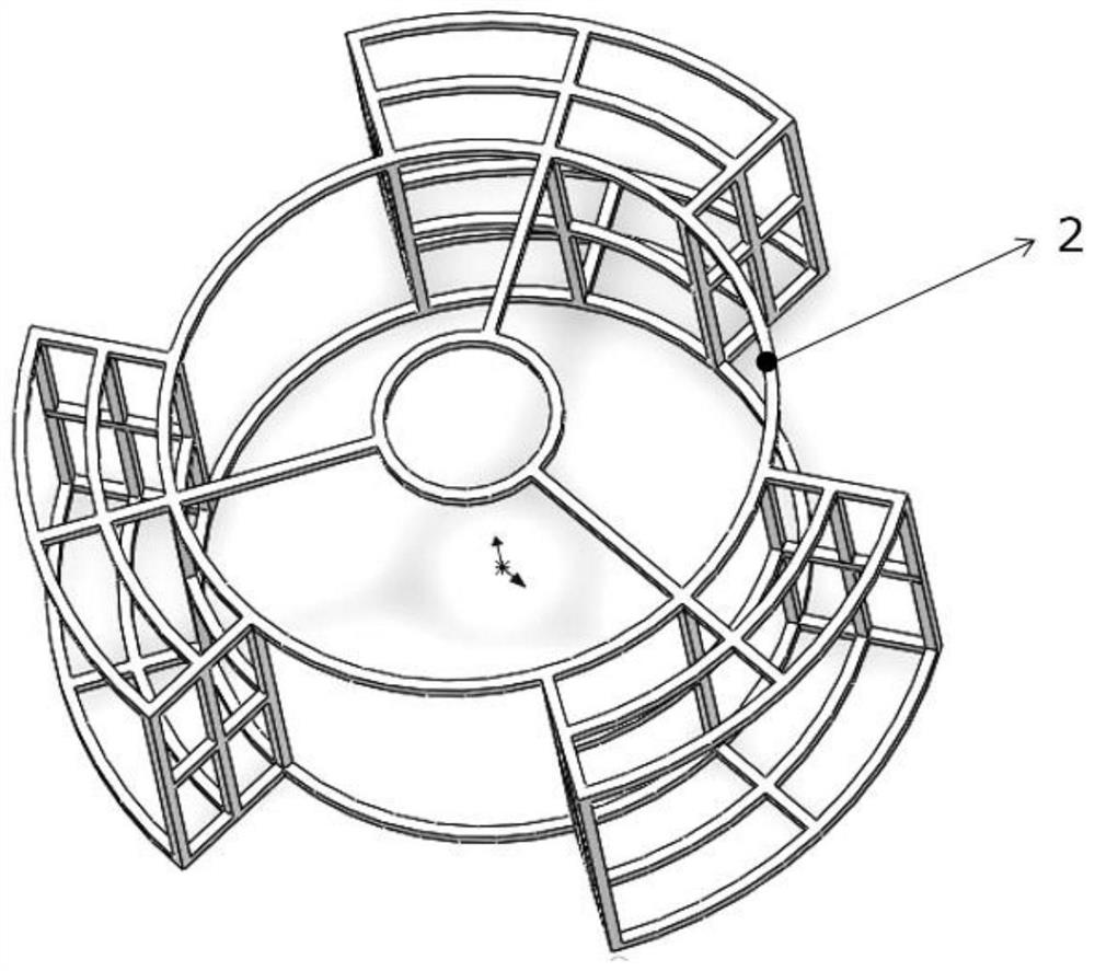
[0033] 1) According to the structure of the reactor, the cage-type catalyst protection frame 2 and the monolithic catalyst 1 are designed;

[0034] In this embodiment, a three-dimensional model of monolithic catalyst 1 is designed, and simulated by using Fluent to obtain monolithic catalyst 3 with optimal structure (mass transfer, heat transfer, conversion efficiency, etc.) under theoretical conditions;

[0035] 2) Use powder bed fusion technology to 3D print cage catalyst protection frame 2;

[0036] 3) The catalytic active agent, ceramic carrier material, and auxiliary materials are mechanically stirred and mixed to form a catalyst 3D printing slurry, and the monolithic catalyst blank is 3D printed by direct writing molding equipment;

[0037] In this embodiment, the catalytic active agent takes 60g titanium silicon powder, the ceramic carrier ...

Embodiment 2

[0041] Embodiment 2, a kind of preparation method of 3D printing can assemble monolithic catalyst, comprises the following steps:

[0042] 1) According to the structure of the reactor, the cage-type catalyst protection frame 2 and the monolithic catalyst 1 are designed;

[0043] In this embodiment, a three-dimensional model of monolithic catalyst 1 is designed, and simulated by using Fluent to obtain monolithic catalyst 3 with optimal structure (mass transfer, heat transfer, conversion efficiency, etc.) under theoretical conditions;

[0044] 2) Use powder bed fusion technology to 3D print cage catalyst protection frame 2;

[0045] 3) Mechanically stir and mix the catalytic active agent, ceramic carrier material, and auxiliary materials into a catalyst 3D printing slurry, and 3D print the monolithic catalyst blank through a direct writing molding device;

[0046] In this embodiment, the catalytic active agent takes 45g titanium silicon powder, the ceramic carrier material is a...

Embodiment 3

[0050] Embodiment 3, a kind of preparation method of 3D printing can assemble monolithic catalyst, comprises the following steps:

[0051] 1) According to the structure of the reactor, the cage-type catalyst protection frame 2 and the monolithic catalyst 1 are designed;

[0052] In this embodiment, a three-dimensional model of monolithic catalyst 1 is designed, and simulated by using Fluent to obtain monolithic catalyst 3 with optimal structure (mass transfer, heat transfer, conversion efficiency, etc.) under theoretical conditions;

[0053] 2) Use powder bed fusion technology to 3D print cage catalyst protection frame 2;

[0054] 3) Mechanically stir and mix the catalytic active agent, ceramic carrier material, and auxiliary materials into a catalyst 3D printing slurry, and 3D print the monolithic catalyst blank through a direct writing molding device;

[0055] In this embodiment, the catalytic active agent takes 30g titanium silicon powder, the ceramic carrier material is a...


PUM

PropertyMeasurementUnit
specific surface areaaaaaaaaaaa

Abstract

The invention discloses a 3D printing assembled monolithic catalyst and a preparation method thereof. The assembled monolithic catalyst comprises a cage type catalyst protection frame mounted on a rotor, and a monolithic catalyst is mounted on the cage type catalyst protection frame. The preparation method comprises the following steps of: designing a cage-type catalyst protection frame and a monolithic catalyst according to the structure of a reaction kettle, and performing 3D printing of the cage-type catalyst protection frame by adopting a powder bed melting technology; then mechanically stirring and mixing a catalytic active agent and a ceramic carrier material to obtain catalyst 3D printing slurry, and carrying out 3D printing of an initial monolithic catalyst blank through direct-writing forming equipment; naturally drying the initial monolithic catalyst blank, and then carrying out a high-temperature sintering process to obtain monolithic catalysts; and finally, uniformly inserting a plurality of monolithic catalysts into the cage type catalyst protection frame to assemble a monolithic catalyst structure. According to the invention, the mechanical strength of the monolithic catalyst is enhanced, the damage of the monolithic catalyst in the reaction process is reduced, and the cyclic utilization function of the monolithic catalyst is fully exerted.

Description

technical field [0001] The invention belongs to the technical field of monolithic catalysts in catalytic reactions, and in particular relates to a 3D printing assembling monolithic catalyst and a preparation method thereof. Background technique [0002] At present, the catalysts commonly used in the industry mainly include packed bed catalysts in the form of particles, supported catalysts, monolithic catalysts, etc.; the monolithic catalysts are made by mixing catalyst active components, binders, etc. in a certain proportion to form a slurry with a certain viscosity. Material, by extruding a catalyst with a specific structure, the structure is mainly a honeycomb structure with neatly arranged parallel channels, which has the advantages of high mass and heat transfer, but the traditional monolithic catalyst with a honeycomb structure has no radial mass transfer and Heat transfer, which can be unfavorable for many applications; this requires the optimization of monolithic cata...

Claims


Application Information

Patent Timeline
Patent Type & Authority Applications(China)
IPC IPC(8): C04B35/14C04B35/622B01J37/00B01J37/08C07C29/48C07C31/20
CPCC04B35/14C04B35/622B01J37/00B01J37/08C07C29/48B33Y10/00B33Y70/10C04B2235/3231C04B2235/6026C04B2235/6562C04B2235/6567C04B2235/96C07C31/202
Inventor 田小永邱正平霍存宝
Owner XI AN JIAOTONG UNIV
Learn More